Page 2 of 11
Re: HDL Implementation of Video Generator Test for 16-bit PV
Posted: Fri Sep 21, 2012 8:19 pm
by ElEctric_EyE
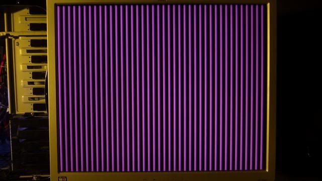
I dove right in and came up with something that looks decent in ISim for a pattern generator using the output's from Arlet's H/V Sync Module. Although it may be a pixel off, the action of it seems to be what I need, even though it won't be much of a pattern yet.
Code: Select all
module patterngen(
						output [4:0] Red_data,
						output [5:0] Green_data,
						output [4:0] Blue_data,
						input pclk,
						input hsync,
						input vsync,
						input hstart,
						input vstart,
						input hblank,
						input vblank
						);

reg [4:0] Red_count = 31;
reg [5:0] Green_count = 63;
reg [4:0] Blue_count = 31;
reg countflag = 1;		//start with 1 since hblank starts with 1 on powerup


always @(posedge pclk)
	if ( hstart | hblank )
		countflag <= ~countflag;	//toggle flag at beginning and end of displayed line

always @(posedge pclk)
	if ( countflag )
		begin
			Red_count <= Red_count - 1;
			Green_count <= Green_count - 1;
			Blue_count <= Blue_count - 1;
		end

assign Red_data = Red_count;
assign Green_data = Green_count;
assign Blue_data = Blue_count;

endmodule
Re: HDL Implementation of Video Generator Test for 16-bit PV
Posted: Fri Sep 21, 2012 8:44 pm
by MichaelM
Don't use tab.
Looks okay to me, and looks like it will generate intensity ramps. I can't say what the colors will be because the red/blue counters have shorter periods than the green counter. It defnitely won't be a grayscale ramp. One thing is for sure, it will be an interesting color pattern.
One HDL coding style note to consider. You can declare your Verilog 2001 color outputs to be reg, and not have to declare the counters separately and make the assignment to the outputs at the bottom as you have done. The synthesis results will be the same, but the HDL will be less wordy:
output reg [4:0] Red_data;
always @(posedge pclk)
if ( countflag )
Red_data <= Red_data - 1;
Haven't tried initializing the reg in the module port list before; will leave that to you to try and post back a note if it is acceptable to the synthesizer and simulator.
Re: HDL Implementation of Video Generator Test for 16-bit PV
Posted: Fri Sep 21, 2012 9:39 pm
by ElEctric_EyE
Hmmm, so you mean it should look like this? ISE text editor auto-indents after comma then return, no tab:
Code: Select all
module patterngen( output [4:0] Red_data,
						 output [5:0] Green_data,
						 output [4:0] Blue_data,
						 input pclk,
						 input hsync,
						 input vsync,
						 input hstart,
						 input vstart,
						 input hblank,
						 input vblank
						 );
Arlet's coding style/technique use the initialization style supported by Verilog for all of the major elements of the module. This provides the initial conditions that the simulator requires. However, be aware that the initialization that is performed using this technique is only applicable on configuration of the FPGA. IOW, it's embedded in the bitstream as the initial reset conditions of the FFs.
...Haven't tried initializing the reg in the module port list before; will leave that to you to try and post back a note if it is acceptable to the synthesizer and simulator.
Basically doing the same thing here right? Yes, it appears to init the reg's correctly in ISim.
Re: HDL Implementation of Video Generator Test for 16-bit PV
Posted: Fri Sep 21, 2012 9:43 pm
by MichaelM
Sorry about that.
Don't hit tab when composing a response. I don't know where the tool goes, but the response is definitely lost in the ether.
I meant something like:
output reg [4:0] Red_data = 31,
Re: HDL Implementation of Video Generator Test for 16-bit PV
Posted: Fri Sep 21, 2012 11:58 pm
by ElEctric_EyE
...I meant something like:
output reg [4:0] Red_data = 31,
Ah, I think I am getting the gist of your suggestions. I ran a ISim based on the modifications, you suggested, and changed my code. It is even more compact. The following is appearing to have the same behavior in ISim:
Code: Select all
module patterngen( output reg [4:0] Red_data = 31,
						 output reg [5:0] Green_data = 63,
						 output reg [4:0] Blue_data = 31,
						 input pclk,
						 input hsync,
						 input vsync,
						 input hstart,
						 input vstart,
						 input hblank,
						 input vblank
						 );

reg countflag = 1;		//start with 1 since hblank starts with 1 on powerup

always @(posedge pclk)
	if ( hstart | hblank )
		countflag <= ~countflag;	//toggle flag at beginning and end of displayed line

always @(posedge pclk)
	if ( countflag )
		begin
			Red_data <= Red_data - 1;
			Green_data <= Green_data - 1;
			Blue_data <= Blue_data - 1;
		end

endmodule
Re: HDL Implementation of Video Generator Test for 16-bit PV
Posted: Sat Sep 22, 2012 7:03 am
by Arlet
Note that pclk isn't a global clock. Maybe ISE is smart enough to use a global clock net, and add all the timing constraints, but I've always avoided it. So instead of:
Code: Select all
always @(posedge pclk)
   if ( hstart | hblank )
      countflag <= ~countflag;
I use the regular clock as clock input, and use the pclk as an enable signal:
Code: Select all
always @(posedge clk50)
   if ( pclk )
      if ( hstart | hblank )
         countflag <= ~countflag;
By the way, I would prefer to write the code like this:
Code: Select all
always @(posedge clk50)
   if ( pclk )
      if ( hstart )
         countflag <= 1;
      else if ( hblank )
         countflag <= 0;
That way you don't have to worry about countflag ending up in the wrong state. After each line it will correct itself.
Re: HDL Implementation of Video Generator Test for 16-bit PV
Posted: Sat Sep 22, 2012 12:12 pm
by ElEctric_EyE
I hear what you're saying about global clocks as pclk is generated from a global clock and cannot be considered one. But I don't think your solution will work on the other matter because hstart and hblank are pulses.
Re: HDL Implementation of Video Generator Test for 16-bit PV
Posted: Sat Sep 22, 2012 12:23 pm
by Arlet
Yes, hstart and hblank are pulses, but they only change when pclk is enabled, so you have just enough time to catch them.
Re: HDL Implementation of Video Generator Test for 16-bit PV
Posted: Sat Sep 22, 2012 12:49 pm
by ElEctric_EyE
Ah, I see that now. It does not come intuitively yet...
EDIT: I remember what I was thinking when I first saw your code:
Code: Select all
always @(posedge clk50)
   if ( pclk )
      if ( hstart | hblank )
I was thinking of an 'AND' gate resulting from the 2 'if' statements, which was incorrect. I was thinking 'if' AND 'if' then 'do this'...
I think I'll try what I have so far tonight.
Re: HDL Implementation of Video Generator Test for 16-bit PV
Posted: Sun Sep 23, 2012 9:31 am
by Arlet
This will synthesise into a flip flop with enable. The enable signal will be controlled by: 'pclk & (hstart | hblank)', and the data input will be an inverted data output (for the first case). In the second case, the enable input is the same, but the data input will be 'hstart'.
Re: HDL Implementation of Video Generator Test for 16-bit PV
Posted: Sun Sep 23, 2012 10:13 am
by ElEctric_EyE
Ah, this is good then. I'm learning, although slowly. I feel like I must be able to picture the circuit from the code...
Got a video signal this morning. Had to change the constraint file, as the RGB assignments are not correct in it. Will do that today on the header post of the 'Concept & Design' thread.
The pattern is not what I was expecting. Not too much of a ramp, but it does seem an even mix of red and blue. I think tonight I will try to get some more tests done to confirm MSB placement and to single out each primary color.
Also, borders seem almost non-existent. The monitor does confirm it is seeing 640x480x59Hz. It is recommending a higher resolution.
EDIT: Found 2 bits for green out of order in the .ucf file. Don't know what I was thinking at the time, probably rushing. Thankfully an easy fix.
Re: HDL Implementation of Video Generator Test for 16-bit PV
Posted: Sun Sep 23, 2012 10:19 am
by Arlet
Ah, this is good then. I'm learning, although slowly. I feel like I must be able to picture the circuit from the code...
That's a good approach. I try to do the same thing, although usually not all the way down to the gory details, but I still try to visualize the general flow with flip flops, muxes, and other logic when writing the verilog.
Re: HDL Implementation of Video Generator Test for 16-bit PV
Posted: Tue Sep 25, 2012 12:58 am
by ElEctric_EyE
Current code:
Code: Select all
module patterngen( output reg [4:0] Red_data = 31,
						 output reg [5:0] Green_data = 63,
						 output reg [4:0] Blue_data = 31,
						 input clk50,
						 input pclk,
						 input hstart,
						 input hblank
						 );

reg countflag;

always @(posedge clk50)
   if ( pclk )
      if ( hstart )
         countflag <= 1;
      else if ( hblank )
         countflag <= 0;

always @(posedge clk50)
	if ( countflag )
		begin
			Red_data <= Red_data - 1;
			Green_data <= Green_data - 1;
			Blue_data <= Blue_data - 1;
		end

endmodule
When I change the last part of the code above to:
Code: Select all
always @(posedge clk50)
	if ( countflag )
		begin
			Red_data <= Red_data - 1;
			Green_data <= 0;
			Blue_data <= 0;
		end
I see 40 Red fading bars, very similar to the original pic above with the vertical purple bars, except more brighter towards the left of each stripe.
When I set the last part to:
Code: Select all
always @(posedge clk50)
	if ( countflag )
		begin
			Red_data <= 0;
			Green_data <= 0;
			Blue_data <= Blue_data - 1;
		end
I am seeing a similar test as the previous Red test, although Blue...
Now green test is different. Thinner bars. Which at this point probably means a soldering problem. I will investigate this anomaly.
Re: HDL Implementation of Video Generator Test for 16-bit PV
Posted: Tue Sep 25, 2012 5:12 am
by Arlet
Code: Select all
always @(posedge clk50)
	if ( countflag )
		begin
			Red_data <= 0;
			Green_data <= 0;
			Blue_data <= Blue_data - 1;
		end
Just like in the other code, you'll need to test for pclk here:
Code: Select all
always @(posedge clk50)
	if (pclk &  countflag )
		begin
			Red_data <= 0;
			Green_data <= 0;
			Blue_data <= Blue_data - 1;
		end
Re: HDL Implementation of Video Generator Test for 16-bit PV
Posted: Tue Sep 25, 2012 11:06 pm
by ElEctric_EyE
@Arlet. I have made the change you suggested...
But at this point, I know I have a soldering issue on the right side of the FPGA, because I see 20 bars which is what I expect when displaying 6-bit Green in a 640 pixel horizontal display, but I ran my thumbnail down the right side of the FPGA, when I did not see the expected pattern, and I was observing changes. Unfortunate. I am not the soldering 'professional' I thought I was.
I will have another go tomorrow, my only day off this week. Also, I do see noise in the video already. I am thinking back to yours and BDD suggestion of braid and excess of solder. It is ugly though. I prefer an ultra fine tip, flux and depend on the solder on the board. But, not enough solder there though...
EDIT: So this could be a bypass issue already surfacing,but I doubt it as this problem is only rearing it's ugly head on the right side of the FPGA. Tomorrow I dedicate the day for some troubleshooting.