Page 10 of 11
Re: HDL Implementation of Video Generator Test for 16-bit PV
Posted: Tue Nov 06, 2012 8:14 pm
by ElEctric_EyE
Added 2 BRAMs to the top_level, 1 for X and 1 for Y co-ordinates. The BRAMs are the dual port syle RAMB16_S18_S18. I also made another LineGen module that just puts the X counter value into the X-BRAM and Y-BRAM. Something is not right, but at least it is semi-functioning! I have a feeling my BRAM enabling logic is wrong, here it is (not the best comments, sorry):
Code: Select all
RAMB16_S18_S18 line1X (
	.CLKA(clk108),
	.ADDRA(Z),
	.DIPA(2'b0),		// write 0
	.DIA(0),
	.DOA(X1),
	.ENA(countflag),		// only in visible area
	.WEA(1'b0),		// always read
	.SSRA(1'b0),

	.CLKB(clk108),
	.ADDRB(Z),
	.DIPB(2'b0),
	.DIB(Xdata),
	.ENB(countflag),
	.SSRB(1'b0),
	.WEB(countflag)		//always write
	);

	RAMB16_S18_S18 line1Y (
	.CLKA(clk108),
	.ADDRA(Z),
	.DIPA(2'b0),		// write 0
	.DIA(0),
	.DOA(Y1),
	.ENA(countflag),		// only in visible area
	.WEA(1'b0),		// always read
	.SSRA(1'b0),

	.CLKB(clk108),
	.ADDRB(Z),
	.DIPB(2'b0),
	.DIB(Ydata),
	.ENB(countflag),
	.SSRB(1'b0),
	.WEB(countflag)		//always write
	);
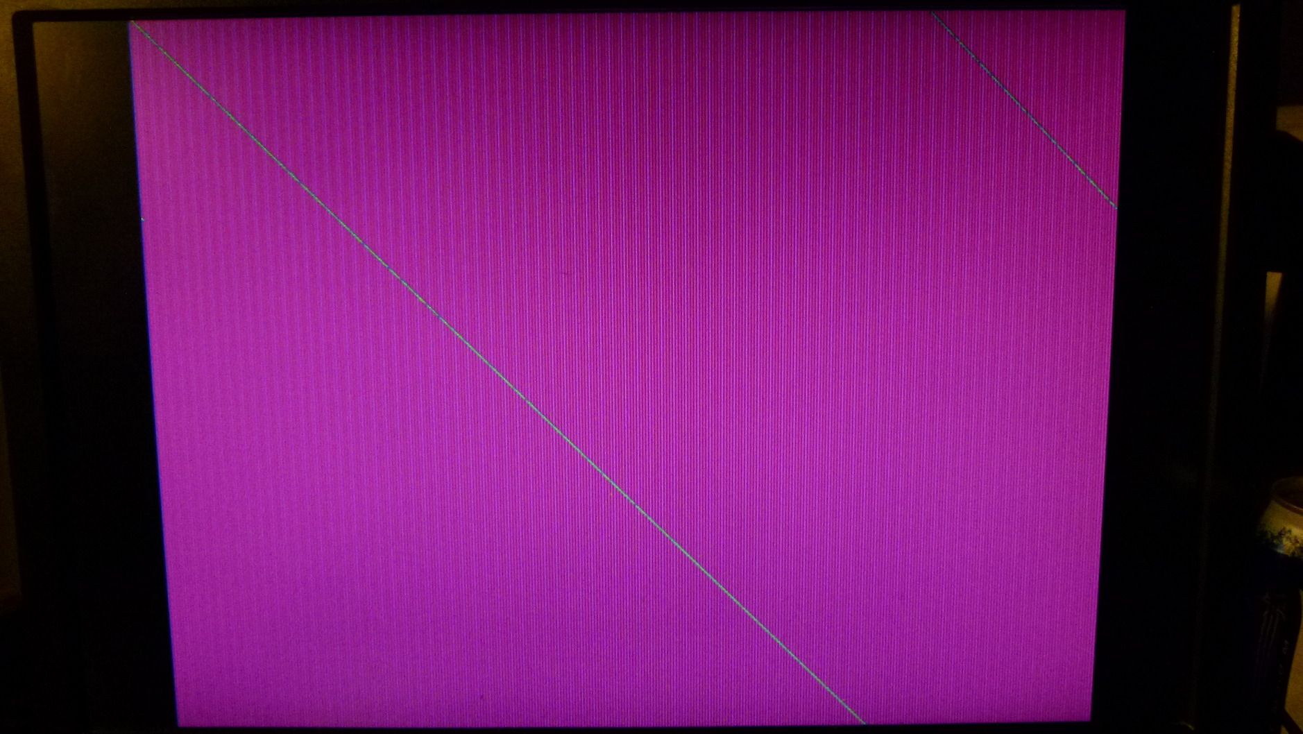
Close-up
pic.
Re: HDL Implementation of Video Generator Test for 16-bit PV
Posted: Tue Nov 06, 2012 8:20 pm
by Arlet
How are the interface signals used (Z, X1, Y1, Xdata, Ydata) ?
One problem is that you are reading and writing from the same address (Z) at the same time, through two different ports. The block RAMs don't support that. The write will work, but the read is undefined. Of course, if you always write the same value, I suppose it'll work.
Re: HDL Implementation of Video Generator Test for 16-bit PV
Posted: Tue Nov 06, 2012 8:34 pm
by ElEctric_EyE
How are the interface signals used (Z, X1, Y1, Xdata, Ydata) ?...
Z is the max distance of
any line based on resolution. In this case it counts to 799 based on 640x480 resolution.
Xdata and Ydata go into the BRAMs from the LineGen module. X1 and Y1 are the outputs of the BRAMs and go to the VDACif module, where it compares X with X1 | Y with Y1, then plots a green pixel.
...One problem is that you are reading and writing from the same address (Z) at the same time, through two different ports. The block RAMs don't support that. The write will work, but the read is undefined. Of course, if you always write the same value, I suppose it'll work.
I will keep an eye on this.
Re: HDL Implementation of Video Generator Test for 16-bit PV
Posted: Tue Nov 06, 2012 8:38 pm
by Arlet
And when are you incrementing Z ? Keep in mind that X equals X1 and Y equals Y1 only for a single pixel in the list, and that you need to have the correct Z at the time.
Re: HDL Implementation of Video Generator Test for 16-bit PV
Posted: Tue Nov 06, 2012 8:54 pm
by ElEctric_EyE
And when are you incrementing Z...
Code: Select all
always @(posedge clk108)
	if ( Z == Zmax )
		Z <= 0;
		else if ( countflag )
			Z <= Z + 1;
I increment Z the same as X, but it resets at 800 not 640...
I am thinking to plot a pixel only when X == X1, not when X == X1 | Y == Y1. This will be my last test before I give in to some rest!
As an auto mechanic, in my field I would be accused of throwing parts at the problem at this point.

Re: HDL Implementation of Video Generator Test for 16-bit PV
Posted: Tue Nov 06, 2012 9:04 pm
by Arlet
You need to plot only when (X==X1) & (Y==Y1), but you can't just cycle through all the Z values at every clock. Suppose you have a list of points: (0,0) (1,1), (2,2). When X==0, Y==0, you plot the first point, and advance Z. Then you need to wait until you hit the next point X==1, Y==1, and then you advance Z again. Naturally, this will only work if you have pre-sorted all the values by Y-then-X (there are also methods that will work with an unsorted list, but this is much more complicated, and takes more time)
You'll also need to be careful with pipeline delays when dealing with horizontal line segments. Incrementing Z, and fetching the next value takes two cycles, but in horizontal cases, you'll need the answer in the next cycle. So, you'd need to pre-increment Z, but keep the output enable deasserted until you have a match.
I recommend running sims rather than throwing parts (and the tool cart) at the problem

Re: HDL Implementation of Video Generator Test for 16-bit PV
Posted: Tue Nov 06, 2012 9:57 pm
by ElEctric_EyE
You need to plot only when (X==X1) & (Y==Y1), but you can't just cycle through all the Z values at every clock. Suppose you have a list of points: (0,0) (1,1), (2,2). When X==0, Y==0, you plot the first point, and advance Z. Then you need to wait until you hit the next point X==1, Y==1, and then you advance Z again. Naturally, this will only work if you have pre-sorted all the values by Y-then-X...
I did try incrementing Z and plot a green pixel when ( X == X1 | Y == Y1 ) and it is MUCH better. Random green flickering pixels very close to the main diagonal line now. Thanks! More leads to follow tomorrow for further experimentation, like your suggested Y priority over X.
Closeup
Re: HDL Implementation of Video Generator Test for 16-bit PV
Posted: Tue Nov 06, 2012 10:09 pm
by ElEctric_EyE
Here's the current ISE13.4 files related to the last pic.
Re: HDL Implementation of Video Generator Test for 16-bit PV
Posted: Wed Nov 07, 2012 7:00 am
by ElEctric_EyE
AHA! I figured it out. My logic was correct, luckily. I should have used the B-side outputs from the BRAMs. Nice clean diagonal line now. A few more experiments now...
A sad note: 2 out of 32 RAM16BWER's used up, meaning only 15 more lines if I continue to use 2 BRAMs for each line drawn. Not a very good use of resources... Maybe I can somehow extrapolate the data out of the one purely diagonal line into all other possible lines.
Re: HDL Implementation of Video Generator Test for 16-bit PV
Posted: Wed Nov 07, 2012 7:06 am
by Arlet
A sad note: 2 out of 32 RAM16BWER's used up, meaning only 15 more lines if I continue to use 2 BRAMs for each line drawn. Not a very good use of resources... Maybe I can somehow extrapolate the data out of the one purely diagonal line into all other possible lines.
True, it's a nice project, but it's not really the best way to store a display full of lines.
Re: HDL Implementation of Video Generator Test for 16-bit PV
Posted: Wed Nov 07, 2012 7:56 am
by ElEctric_EyE
Yeah, although it is probably the fastest way, but too high a price.
I need to start working with the external RAM I think.
Re: HDL Implementation of Video Generator Test for 16-bit PV
Posted: Wed Nov 07, 2012 4:56 pm
by ElEctric_EyE
Looking at the modifications I made to the code to get the dualport BRAM working made me realize that I didn't need a DP BRAM.
I successfully used the older Spartan 3 RAMB16_S18 primitive, and used 1/2 the resources as the DP BRAM. Facing the reality of this, since the RAMB16_S18 is 1024X16, the max resolution to fully take advantage of this would be 800x600, with the longest diagonal possible @1000 pixels.
I'm still going to push forward with this hardware line drawing, as I really would like to see my spinning 3D cube go at max speed. Working on my logic as it is not 100% yet...
Re: HDL Implementation of Video Generator Test for 16-bit PV
Posted: Wed Nov 07, 2012 5:17 pm
by Arlet
All BRAMs are dual ported, so the single port uses the same amount of resources as the dual port BRAM.
Re: HDL Implementation of Video Generator Test for 16-bit PV
Posted: Wed Nov 07, 2012 7:25 pm
by ElEctric_EyE
I see you're right, I must've been in the middle of an experiment that disabled one of the BRAMs.
Re: HDL Implementation of Video Generator Test for 16-bit PV
Posted: Wed Nov 07, 2012 7:40 pm
by Arlet
I did notice that the documentation also mentions a RAMB8, which is double ported, but only half the size. This could be very useful for small FIFOs.
Another option would be to store only the end points of the lines, and generate the lines dynamically. This is not a beginner's project, though