Page 9 of 11
Re: HDL Implementation of Video Generator Test for 16-bit PV
Posted: Wed Oct 31, 2012 3:21 pm
by ElEctric_EyE
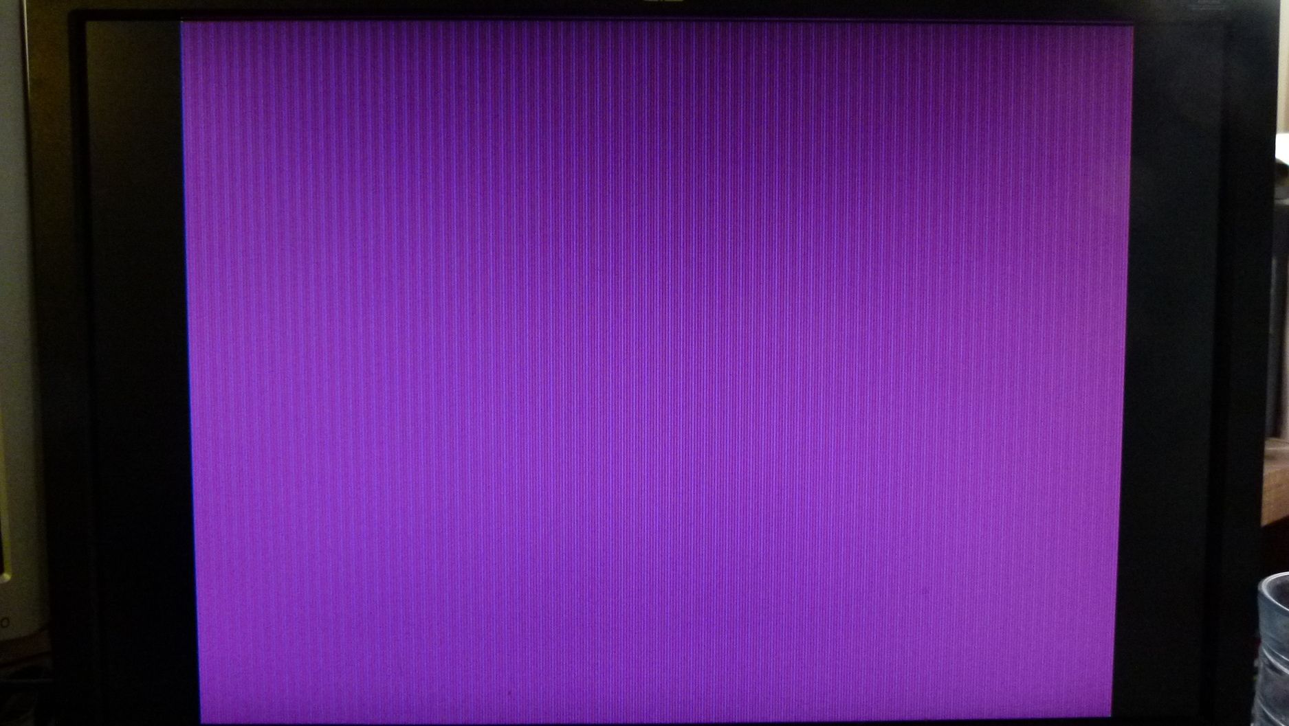
Got it working on the LCD monitor! To make it useful and make sure that my timings are correct, I successfully plotted a green pixel @ (0,0) and also @ (639,479). The hardware in the LCD seems to automatically trim off the borders. Now, I would like to draw lines in hardware. I'll look at FPGA4FUN and openVGA project for clues. I'll work on getting the CRT working abit later...
LARGE pic.
Code: Select all
module VDACif( input clk108,
					input hstart,
					input vstart,
					input hblank,
					input vblank,
					input VSYNCout,
					output reg [4:0] Red_data = 0,
					output reg [5:0] Green_data = 0,
					output reg [4:0] Blue_data = 0,
					output reg DACBLANKn = 1
					);

reg countflag;
reg [9:0] X = 0;
reg [8:0] Y = 0;

parameter
Xmax = 640,
Ymax = 480;

always @(posedge clk108)
      if ( hstart )
         countflag <= 1;									//countflag active in display area
      else if ( hblank )
         countflag <= 0;

always @(posedge clk108)
	if ( countflag )
		X <= X + 1;												//count inside the border
		else
			X <= 0;

always @(posedge clk108)
	if ( X == Xmax )
		Y <= Y + 1;
	 else if ( Y == Ymax )
		Y <= 0;

always @(posedge clk108)								//outgoing data to videoDAC
	if ( countflag & (( X == 0 & Y == 0 ) | ( X == 639 & Y == 479 ))) begin
		Red_data <= 0;
		Green_data <= 6'b111111;
		Blue_data <= 0;									//Priority 1, plot green pixel at Min & Max corners
	end
		else if ( vblank & VSYNCout ) begin
			Red_data <= 0;
			Green_data <= 0;
			Blue_data <= 0;								//Priority 2, send black during vertical retrace
		end
		else if ( !countflag ) begin
			Red_data <= 0;
			Green_data <= 0;
			Blue_data <= 5'b11111;						//Priority 3, blue border
		end
		else if ( X[0] ) begin
			Red_data <= 5'b11111;
			Green_data <= 0;
			Blue_data <= 0;								//Priority 4, odd pixels red
		end
			else begin
				Red_data <= 0;
				Green_data <= 0;
				Blue_data <= 5'b11111;					// even pixels blue
			end

endmodule
Re: HDL Implementation of Video Generator Test for 16-bit PV
Posted: Wed Oct 31, 2012 3:24 pm
by Arlet
Do you want to draw lines on a bitmap, and then display the bitmap ? Or do you want to generate lines on the fly, as you generate the display (
display list)
Re: HDL Implementation of Video Generator Test for 16-bit PV
Posted: Wed Oct 31, 2012 3:39 pm
by ElEctric_EyE
I think for now, no bitmap, only because soon I would like to make another PVB and have it output what I'm working on now into the second PVB. Then maybe at this point have it go into the frame buffer of the 2nd PVB.
Re: HDL Implementation of Video Generator Test for 16-bit PV
Posted: Wed Oct 31, 2012 3:57 pm
by Arlet
What version board are you using by the way? Is this still the first one, or did you assemble one of the new boards ? Anyway, line drawing is not the easiest thing to do, either with bit map or display list. Maybe you should try a text display. FPGA4FUN has an example, and it's a useful thing to have. You can make one with block RAMs, and then attach a CPU to the other port of the block RAM to provide a text output.
Re: HDL Implementation of Video Generator Test for 16-bit PV
Posted: Wed Oct 31, 2012 4:16 pm
by ElEctric_EyE
What version board are you using by the way? Is this still the first one, or did you assemble one of the new boards ?...
This is still the first one, v1.0g, without the very useful pushbuttons present on v1.0h. I sent you 1 v1.0h board, so I have 2 of them on standby...
I was looking at openVGA and I don't see any line drawing modules. I guess he draws triangles using one of his processors, I'm guessing the TTA16 that runs at 140MHz.
I don't think it would be that difficult, after all it is a repetitive over/down/plot-over/down/plot or over/up/plot-over/up/plot, etc. If I could do it in hardware, I can only imagine the speed! This was the reason I wanted to learn Verilog in the first place, so I am eager to do this.
Re: HDL Implementation of Video Generator Test for 16-bit PV
Posted: Wed Oct 31, 2012 4:28 pm
by Arlet
Drawing on a bitmap requires first having a bitmap, plus a read channel for the display output, and a read/write channel for a processor that can draw lines. This already requires a fairly complicated bunch of logic for the memory interface. And if you want to draw the actual lines in hardware, it will take even more.
Re: HDL Implementation of Video Generator Test for 16-bit PV
Posted: Wed Oct 31, 2012 5:42 pm
by ElEctric_EyE
Well, I thought I would have 1 module similar to the one I have now that would plot the pixels from 2 10-bit wide, 800 deep RAMs. 800 being the longest possible line for 640x480. 1 RAM containing X, the other Y values. Another module would calculate the values to be stored in the RAMs, from some registers containing Xstart, Ystart, Xend, and Yend. Another register would hold the color info.
What do you think?
Re: HDL Implementation of Video Generator Test for 16-bit PV
Posted: Wed Oct 31, 2012 5:52 pm
by Arlet
I see, you want to use the RAM (block RAM I suppose) to hold a list of pixels. It would work, but you would have to keep the pixels sorted (first by Y then by X) so you can retrieve them in the order that you need them. If you generate them top-down, left-to-right, then they automatically show up in the right order.
Re: HDL Implementation of Video Generator Test for 16-bit PV
Posted: Wed Oct 31, 2012 6:28 pm
by ElEctric_EyE
I see, you want to use the RAM (block RAM I suppose) to hold a list of pixels...
Yes, so this blockRAM should be instantiated on the top_level? Will it still be a RAMB16BWER dual-port type, just 1 port always read and 1 port always write?
Re: HDL Implementation of Video Generator Test for 16-bit PV
Posted: Wed Oct 31, 2012 7:12 pm
by Arlet
Yes, that'll work.
Re: HDL Implementation of Video Generator Test for 16-bit PV
Posted: Tue Nov 06, 2012 8:14 pm
by ElEctric_EyE
Added 2 BRAMs to the top_level, 1 for X and 1 for Y co-ordinates. The BRAMs are the dual port syle RAMB16_S18_S18. I also made another LineGen module that just puts the X counter value into the X-BRAM and Y-BRAM. Something is not right, but at least it is semi-functioning! I have a feeling my BRAM enabling logic is wrong, here it is (not the best comments, sorry):
Code: Select all
RAMB16_S18_S18 line1X (
	.CLKA(clk108),
	.ADDRA(Z),
	.DIPA(2'b0),		// write 0
	.DIA(0),
	.DOA(X1),
	.ENA(countflag),		// only in visible area
	.WEA(1'b0),		// always read
	.SSRA(1'b0),

	.CLKB(clk108),
	.ADDRB(Z),
	.DIPB(2'b0),
	.DIB(Xdata),
	.ENB(countflag),
	.SSRB(1'b0),
	.WEB(countflag)		//always write
	);

	RAMB16_S18_S18 line1Y (
	.CLKA(clk108),
	.ADDRA(Z),
	.DIPA(2'b0),		// write 0
	.DIA(0),
	.DOA(Y1),
	.ENA(countflag),		// only in visible area
	.WEA(1'b0),		// always read
	.SSRA(1'b0),

	.CLKB(clk108),
	.ADDRB(Z),
	.DIPB(2'b0),
	.DIB(Ydata),
	.ENB(countflag),
	.SSRB(1'b0),
	.WEB(countflag)		//always write
	);
Close-up
pic.
Re: HDL Implementation of Video Generator Test for 16-bit PV
Posted: Tue Nov 06, 2012 8:20 pm
by Arlet
How are the interface signals used (Z, X1, Y1, Xdata, Ydata) ?
One problem is that you are reading and writing from the same address (Z) at the same time, through two different ports. The block RAMs don't support that. The write will work, but the read is undefined. Of course, if you always write the same value, I suppose it'll work.
Re: HDL Implementation of Video Generator Test for 16-bit PV
Posted: Tue Nov 06, 2012 8:34 pm
by ElEctric_EyE
How are the interface signals used (Z, X1, Y1, Xdata, Ydata) ?...
Z is the max distance of
any line based on resolution. In this case it counts to 799 based on 640x480 resolution.
Xdata and Ydata go into the BRAMs from the LineGen module. X1 and Y1 are the outputs of the BRAMs and go to the VDACif module, where it compares X with X1 | Y with Y1, then plots a green pixel.
...One problem is that you are reading and writing from the same address (Z) at the same time, through two different ports. The block RAMs don't support that. The write will work, but the read is undefined. Of course, if you always write the same value, I suppose it'll work.
I will keep an eye on this.
Re: HDL Implementation of Video Generator Test for 16-bit PV
Posted: Tue Nov 06, 2012 8:38 pm
by Arlet
And when are you incrementing Z ? Keep in mind that X equals X1 and Y equals Y1 only for a single pixel in the list, and that you need to have the correct Z at the time.
Re: HDL Implementation of Video Generator Test for 16-bit PV
Posted: Tue Nov 06, 2012 8:54 pm
by ElEctric_EyE
And when are you incrementing Z...
Code: Select all
always @(posedge clk108)
	if ( Z == Zmax )
		Z <= 0;
		else if ( countflag )
			Z <= Z + 1;
I increment Z the same as X, but it resets at 800 not 640...
I am thinking to plot a pixel only when X == X1, not when X == X1 | Y == Y1. This will be my last test before I give in to some rest!
As an auto mechanic, in my field I would be accused of throwing parts at the problem at this point.
