65c816 "Core"

Building your first 6502-based project? We'll help you get started here.
User avatar
BigDumbDinosaur
Posts: 9425
Joined: 28 May 2009
Location: Midwestern USA (JB Pritzker’s dystopia)
Contact:

Re: 65c816 "Core"

Post by BigDumbDinosaur »

GamerFox wrote:
Here's the new version of the sheet with the advice you gave me, and I'm a little afraid of cranking up phi2 too high to warrant memory bus ack lines.

According to the Maxim data sheet for the DS1233, the capacitor connected between reset and ground (C108) should be no larger than 0.01µF.

On the first page, I see some regulators with what looks to be zener diodes attached to the regulators' outputs. What are the zeners expected to do?

Otherwise, it looks as though you are good to go.
x86?  We ain't got no x86.  We don't NEED no stinking x86!
GamerFox
Posts: 32
Joined: 18 Mar 2021

Re: 65c816 "Core"

Post by GamerFox »

BigDumbDinosaur wrote:
On the first page, I see some regulators with what looks to be zener diodes attached to the regulators' outputs. What are the zeners expected to do?
For the life of me, I can't remember. I remember seeing it in one of Recom's application notes, either for overvoltage or reverse voltage protection.
User avatar
BigDumbDinosaur
Posts: 9425
Joined: 28 May 2009
Location: Midwestern USA (JB Pritzker’s dystopia)
Contact:

Re: 65c816 "Core"

Post by BigDumbDinosaur »

GamerFox wrote:
BigDumbDinosaur wrote:
On the first page, I see some regulators with what looks to be zener diodes attached to the regulators' outputs. What are the zeners expected to do?
For the life of me, I can't remember. I remember seeing it in one of Recom's application notes, either for overvoltage or reverse voltage protection.

Garth reminded me that back in the day, we used to place a zener that way to protect the circuit from an overshoot that sometimes occurred at power-on. Regulators have improved a lot since "back in the day," and I have not done that in probably 25 years. It won't hurt, of course, so if it being there gives you a warm, fuzzy feeling... :D
x86?  We ain't got no x86.  We don't NEED no stinking x86!
User avatar
Dr Jefyll
Posts: 3525
Joined: 11 Dec 2009
Location: Ontario, Canada
Contact:

Re: 65c816 "Core"

Post by Dr Jefyll »

BigDumbDinosaur wrote:
Garth reminded me that back in the day, we used to place a zener that way to protect the circuit from an overshoot that sometimes occurred at power-on.
Of course switching regulators like this weren't available back in the day, but it's well known that linear regulators require a protection diode in certain circumstances, the goal being to prevent current from flowing backwards through the regulator at powerdown.

Although superficially that may seem impossible, it can occur in certain circumstances. For example, the circuit (the load) attached to the regulator output may include considerable capacitance due to the bypass caps that are present, and that capacitance will contain stored energy. At powerdown, that energy needs to be discharged, and if the regulator input voltage plummets too rapidly, current will pass backwards through the regulator (unless the protection diode is present).

A look at the Recom datasheet (attached) reveals that their handy little switching regulator likewise faces that powerdown issue, and a protection diode may be required for that reason. (The datasheet also suggests a minimum load of 10 mA, which presumably explains GamerFox's inclusion of R2 and R3.)
R-78-1.0.pdf
(675.15 KiB) Downloaded 40 times
R-785.0-1.0 protection.png
minimum-load resistors.png
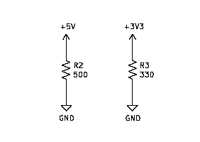
minimum-load resistors.png (1.62 KiB) Viewed 816 times
The datasheet doesn't mention zener (or other) diodes shunted to ground, so I'm drawing a blank on that subject. If such a precaution were necessary you'd think the datasheet would mention it. But possibly the App Note GamerFox mentioned explains it. (I'm also drawing a blank on zener diodes being used as shunts for linear regulators back in the day. Maybe Garth can clarify.)

GamerFox wrote:
I'm a little afraid of cranking up phi2 too high to warrant memory bus ack lines.
Um... bus ack lines? Not sure what you could mean by that. The Motorola 68000 bus protocol involves a Data Transfer Acknowledge signal, but there's nothing similar in the 65xx context. If you wanna overclock a 65xx you can just keep cranking up phi2 as far as you like. At some point your system will go off into the weeds, and that's how you know you've gone too far! :P

-- Jeff
In 1988 my 65C02 got six new registers and 44 new full-speed instructions!
https://laughtonelectronics.com/Arcana/ ... mmary.html
User avatar
GARTHWILSON
Forum Moderator
Posts: 8773
Joined: 30 Aug 2002
Location: Southern California
Contact:

Re: 65c816 "Core"

Post by GARTHWILSON »

Dr Jefyll wrote:
BigDumbDinosaur wrote:
Garth reminded me that back in the day, we used to place a zener that way to protect the circuit from an overshoot that sometimes occurred at power-on.
Of course switching regulators like this weren't available back in the day, but it's well known that linear regulators require a protection diode in certain circumstances, the goal being to prevent current from flowing backwards through the regulator at powerdown.
My comment came specifically from using one of Power Trends' integrated switching regulators, the 78SR112 12V regulator, in a design in 1994. You can see it here as the approximately 1" square black thing with the "#12" label on it.
Image
It's kind of a thermoplastic box with the other side open where you can see the components in it. They required a 5W ZD at the output to shunt out turn-on overshoot. I don't know why they didn't just integrate it into the integrated switching regulator.
http://WilsonMinesCo.com/ lots of 6502 resources
The "second front page" is http://wilsonminesco.com/links.html .
What's an additional VIA among friends, anyhow?
User avatar
Dr Jefyll
Posts: 3525
Joined: 11 Dec 2009
Location: Ontario, Canada
Contact:

Re: 65c816 "Core"

Post by Dr Jefyll »

Thanks, Garth. Switching reg's have gotten quite a lot smaller but evidently they did and still do need a zener shunt sometimes.

I spent some time looking around at http://www.recom-power.com but I was unable to locate the App Note GamerFox mentioned. But presumably the App Note is where the zener part numbers in the schematic (BZX79C5V6-T50A and BZX79C3V6) came from, isn't that right, Gamerfox ?

-- Jeff
In 1988 my 65C02 got six new registers and 44 new full-speed instructions!
https://laughtonelectronics.com/Arcana/ ... mmary.html
User avatar
GARTHWILSON
Forum Moderator
Posts: 8773
Joined: 30 Aug 2002
Location: Southern California
Contact:

Re: 65c816 "Core"

Post by GARTHWILSON »

Here's the inside:
PT78SR112inside.jpg
PT78SR112inside.jpg (45.23 KiB) Viewed 798 times

It's an 18-watt regulator. Since the board is not all way way down in the box, there may be parts on the back, too (or maybe it's only the other half of the inductor core).
http://WilsonMinesCo.com/ lots of 6502 resources
The "second front page" is http://wilsonminesco.com/links.html .
What's an additional VIA among friends, anyhow?
GamerFox
Posts: 32
Joined: 18 Mar 2021

Re: 65c816 "Core"

Post by GamerFox »

Dr Jefyll wrote:
Thanks, Garth. Switching reg's have gotten quite a lot smaller but evidently they did and still do need a zener shunt sometimes.

I spent some time looking around at http://www.recom-power.com but I was unable to locate the App Note GamerFox mentioned. But presumably the App Note is where the zener part numbers in the schematic (BZX79C5V6-T50A and BZX79C3V6) came from, isn't that right, Gamerfox ?

-- Jeff
Originally it was MMSZ4690T1G and MMSZ4685T1G but they were SMD-only

e: it's in this sheet https://recom-power.com/pdf/Innoline/R-78C-1.0.pdf
GamerFox
Posts: 32
Joined: 18 Mar 2021

Re: 65c816 "Core"

Post by GamerFox »

I took BDD's advice and changed the memory mapping a little. Here's the decoder circuit sheet.
Attachments
address-Address.pdf
(48.73 KiB) Downloaded 45 times
User avatar
GARTHWILSON
Forum Moderator
Posts: 8773
Joined: 30 Aug 2002
Location: Southern California
Contact:

Re: 65c816 "Core"

Post by GARTHWILSON »

GamerFox wrote:
I took BDD's advice and changed the memory mapping a little. Here's the decoder circuit sheet.
That's an awful lot of gate delays. Have you added up all the timings and seen if it's still workable?
http://WilsonMinesCo.com/ lots of 6502 resources
The "second front page" is http://wilsonminesco.com/links.html .
What's an additional VIA among friends, anyhow?
J64C
Posts: 239
Joined: 11 Jul 2021

Re: 65c816 "Core"

Post by J64C »

GARTHWILSON wrote:
GamerFox wrote:
I took BDD's advice and changed the memory mapping a little. Here's the decoder circuit sheet.
That's an awful lot of gate delays. Have you added up all the timings and seen if it's still workable?
Mixing and matching the HC and LS types might not be ideal either.

But yeah, that amount of gates, there’d be a solid 50-60nS delay going on there.
kernelthread
Posts: 166
Joined: 23 Jun 2021

Re: 65c816 "Core"

Post by kernelthread »

The actual logic also looks incorrect. The "BANKZERO" signal, labelled with no bar, is actually active low. Any access to bank 0 would result in all four output selects (nEXTRAMSEL, nROMSEL, nIOSEL, nLORAMSEL) all going high, i.e. inactive.
This sort of thing is a good application for a PLD of some sort. If you could make do with 7 IO chip selects instead of 8 and 4 bank address bits (1MB address space), you could fit it all onto a 22V10. Even better, if you used a 1502/7032 you could fit the bank select latch on there as well.
GamerFox
Posts: 32
Joined: 18 Mar 2021

Re: 65c816 "Core"

Post by GamerFox »

If I were to go use a 22v10 it looks like I'd have to change the primary power rail to 5V leading to needing level shifters for the SD card and display.
User avatar
floobydust
Posts: 1394
Joined: 05 Mar 2013

Re: 65c816 "Core"

Post by floobydust »

GamerFox wrote:
If I were to go use a 22v10 it looks like I'd have to change the primary power rail to 5V leading to needing level shifters for the SD card and display.
You can use the low voltage version, the ATF22LV10C-10PU. It's rated for use down to 3.0 volts and has a 10ns rating. I was going to suggest this, but you already did yourself :wink:
User avatar
drogon
Posts: 1671
Joined: 14 Feb 2018
Location: Scotland
Contact:

Re: 65c816 "Core"

Post by drogon »

GamerFox wrote:
If I were to go use a 22v10 it looks like I'd have to change the primary power rail to 5V leading to needing level shifters for the SD card and display.
Not sure about the display, but there are many microSD card modules that run from 5v and have the level shifters built in (and provide a handy 0.1" pin header thing)

I'm using them on my Ruby boards which are all 5v.

-Gordon
--
Gordon Henderson.
See my Ruby 6502 and 65816 SBC projects here: https://projects.drogon.net/ruby/
Post Reply