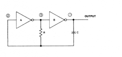
Adapted from an old RCA App Note, here's an oscillator that doesn't require a Schmitt trigger inverter such as 74HC
14 or 74AC
14. Instead, you can use an ordinary inverter such as 74HC
04 or 74AC
04, which you probably already have in your junk box!

(74
LS04 is not a good choice, however.)
Attachment:
 oscillator 1.png [ 22.25 KiB | Viewed 519 times ]
For a simple functional test of a 6502 or 65C02 the exact frequency isn't critical, but somewhere around 0.5 to 1 MHz will be satisfactory. If R is 2.2K then a capacitor of 250 pF to 500 pF should be about right. As with the
oscillator Garth posted, raising the resistance and/or the capacitance will decrease the frequency. For example, doubling R will halve the frequency.
Decreasing R or C has the opposite effect, but R values much below 2K aren't advisable, so if you want frequencies above 1 MHz then decreased capacitance is a better way to go.
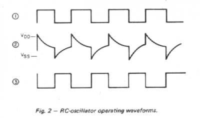
Point 1 in the circuit will always be high when Point 3 is low, and vice versa. Hence, the capacitor C will always be charging or discharging as a result of current through resistor R, and the voltage at Point 2 will ramp down, toggle, then ramp up again as shown in the middle trace below. The toggle happens when the voltage at Point 2 crosses the input transition for inverter A. Inverter A's output will change state and a new half-cycle commences.
Attachment:
 waveforms.png [ 37.45 KiB | Viewed 519 times ]
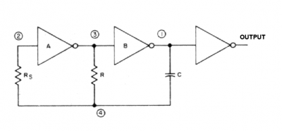
The version below has two minor improvements. According to RCA, the new resistor Rs tends to reduce variations in frequency resulting from variations in the supply voltage. (Unimportant, for a basic test of a 6502.) And to that I'd add that it limits the current passing through the input protection diodes of inverter A as they clamp the peaks of the spiky waveform. Because capacitor C is charged to approximately 50%, not 100 or 0, at each point when a toggle occurs, we can guesstimate that positive spikes at Point 4 will be Vcc/2 above Vcc, and likewise the negative spikes will fall Vcc/2 below ground. These peaks are reduced to the extent of the forward voltage drop of the protection diodes. So, if Vcc/2 is on the same small scale as the forward drop of a diode then little to no clamping occurs. But as Vcc rises the degree of clamping increases, and Rs assumes more importance (as a limiting factor to avoid, as RCA says, variations in frequency resulting from variations in the supply voltage).
The value of Rs isn't critical but I'd size it at 3 to 5 times the value of R, or as high as you wish, really up to the point where PCB leakage currents become a problem and/or R becomes large enough to result in excessive delay due to the RC formed with the inverter's 5 or 10 pF of input capacitance.
As for the extra inverter, this has a buffering effect that may be desirable, especially if the value of R is reduced below 2K.
Attachment:
 oscillator 2.png [ 28.03 KiB | Viewed 519 times ]
-- Jeff
[ edits ]
_________________
In 1988 my 65C02 got six new registers and 44 new full-speed instructions!
https://laughtonelectronics.com/Arcana/ ... mmary.html


