6502.org Forum  Projects  Code  Documents  Tools  Forum
It is currently Wed Oct 02, 2024 12:33 pm

All times are UTC


Post new topic Reply to topic  [ 66 posts ]  Go to page Previous  1, 2, 3, 4, 5  Next
Author Message
PostPosted: Sun Nov 29, 2020 1:35 am 
Offline

Joined: Wed Jun 17, 2020 10:51 am
Posts: 60
hello again

after over a month I come here with another problem :) A lot lot lot of debugging with very little free time .....

In my design I have a 8k window in the 64kByte address space to map in the VGA memory or future memory expansions. That worked as expected when using 2kByte HT6116-70ns SRAM. But when I used IS61C5128 in the same environment - with 8 address bits set to 0 - something strange happened. Sometimes writes would modify 2 or more addresses with the same value. I think I finally figured out the reason for that - take a look at this capture from the logic analyzer.
Attachment:
logic_Analyzer-why sometimes several addresses get changed - 01-a.jpg
logic_Analyzer-why sometimes several addresses get changed - 01-a.jpg [ 58.65 KiB | Viewed 1108 times ]

Attachment:
logic_Analyzer-why sometimes several addresses get changed - 02a.jpg
logic_Analyzer-why sometimes several addresses get changed - 02a.jpg [ 52.11 KiB | Viewed 1108 times ]

The addresses change before CE and RW lines go high. I guess the fast RAM just has enough margin to write additional cells before CE/RW go high.
I have an idea how to solve that - put in a buffer on the address lines (2 74xx574 chips) instead of the 245 I need anyway and trigger them on the rising clock pulse.
Any better ideas?

_________________
No simulation survives contact with reality!


Top
 Profile  
Reply with quote  
PostPosted: Sun Nov 29, 2020 2:30 am 
Offline
User avatar

Joined: Sun Oct 18, 2015 11:02 pm
Posts: 428
Location: Toronto, ON
Try qualifying R/W with PHI2 to derive a /WE signal for RAM, like this:
Attachment:
88FF8AD8-FB2E-40C3-9E26-CE95FB7E6145.jpeg
88FF8AD8-FB2E-40C3-9E26-CE95FB7E6145.jpeg [ 18.99 KiB | Viewed 1103 times ]
Other signals going to RAM usually trail the fall of PHI2 by some margin and will therefore hold steady while /WE is low. That should prevent other addresses from being modified by the write.

_________________
C74-6502 Website: https://c74project.com


Top
 Profile  
Reply with quote  
PostPosted: Sun Nov 29, 2020 2:39 am 
Offline
User avatar

Joined: Fri Aug 30, 2002 1:09 am
Posts: 8521
Location: Southern California
Drass posted while I was searching for any way you might have to keep RAM from being written to when phase 2 is low. I did not find any. From the address-decoding page of the 6502 primer, about 70% of the way down the page: "You must have a way to make sure RAM cannot be written when Φ2 is low! Looking at the 6502's timing diagrams in the data sheet, you will see that the address lines are not guaranteed to be valid and stable before the R/W goes low; so it is possible to write to unintended addresses."

_________________
http://WilsonMinesCo.com/ lots of 6502 resources
The "second front page" is http://wilsonminesco.com/links.html .
What's an additional VIA among friends, anyhow?


Top
 Profile  
Reply with quote  
PostPosted: Sun Jan 31, 2021 5:22 am 
Offline

Joined: Wed Jun 17, 2020 10:51 am
Posts: 60
so that was a long break, but when COVID hits your son's daycare suddenly all free time evaporates. At least no one in my family got sick :)

Last report was on write problems to the DIMM. I could solve that issue by converting to CPU R/W line into a 20ns pulse, so that writes happen only during a short period of the complete 6502 write cycle. That solved all issues, and I could program the memory to generate all SYNC signals correctly. Unfortunately .... when I hooked up to the monitor it would not synchronize. The reason was simple. The monitor did not recognize the 640x400 resolution I had programmed, but tried instead to go to 720x400.

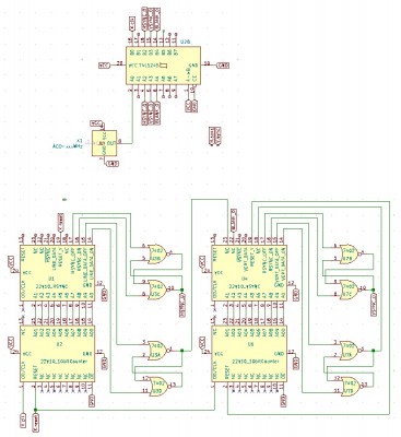
At that point my plan to be able to switch between various resolutions vaporized. Looks like modern LCD monitors are not truly multisync, but have a number of fixed frequencies programmed in. I have to stick to standard VGA, and with that in mind using a programmable memory did not make sense anymore. So I decided to do SYNC generation with 2 more GALs and 2 74LS00:
Attachment:
New VSYNC generation.jpg
New VSYNC generation.jpg [ 189.42 KiB | Viewed 999 times ]

The code for HSYNC GAL:
Code:
Name     hsync_v05;
PartNo   00 ;
Date     1/7/2021 ;
Revision 01 ;
Designer Engineer ;
Company  private ;
Assembly None ;
Location  ;
Device   g22v10 ;

Pin   1 = clk; /* Clock input */
Pin   2 = A0;
Pin   3 = A1;
Pin   4 = A2;
Pin   5 = A3;
Pin   6 = A4;
Pin   7 = A5;
Pin   8 = A6;
Pin   9 = A7;
Pin  10 = A8;
Pin  11 = A9;


/** Outputs ***********************************************************/
PIN  19  = COUNT_Y;
PIN  20  = LINE_DATA;
PIN  21  = !HSYNC;
PIN  14  = LINE_DATA_ON;
PIN  15  = LINE_DATA_OFF;
PIN  16  = HSYNC_ON;
PIN  17  = HSYNC_OFF;

/*
000      0000000000
.....
256      0100000000   
...
512      1000000000   !A9 #
512      1000000001   A9 & !A8 &!A7
...
639      1001111111   ----
640      1010000000   no signal
....
655      1010001111   -----
....            L1:     A9 & !A8 & A7  & !A6 &  A4
....                         L2:   # A9 & !A8 & A7  &  A6 & !A5 &  A4
...                           L3:   # A9 & !A8 & A7  &  A6 &       !A4
...             L4:   # A9 & !A8 & A7  &  A5 &       !A4
656      101 001 0000   L1
          010      L4
          011      L1
          100      L3
          101      L2
751      101 110 1111   L3 -----
752      101 111 0000   no signal
...
800      1100100000
*/

HSYNC =  A9 & !A8 & A7  & !A6 &        A4
   # A9 & !A8 & A7  &  A6 & !A5 &  A4
   # A9 & !A8 & A7  &  A6 &       !A4
   # A9 & !A8 & A7  &  A5 &       !A4 ;

LINE_DATA = !A9
      #A9 & !A8 & !A7 ;

LINE_DATA_ON  = !A9 & !A8 & !A7 & !A6 & !A5 & !A4 & !A3 & !A2 & !A1 & !A0
      # A9 & A8 & A5;
LINE_DATA_OFF =  A9 & !A8 &  A7 & !A6 & !A5 & !A4 & !A3 & !A2 & !A1 & !A0;
HSYNC_ON      =  A9 & !A8 &  A7 & !A6 & !A5 &  A4 & !A3 & !A2 & !A1 & !A0;
HSYNC_OFF     =  A9 & !A8 &  A7 &  A6 &  A5 &  A4 & !A3 & !A2 & !A1 & !A0;

COUNT_Y = A9 & A8 & A5;

The code for VSYNC GAL
Code:
Name     vsync_v06;
PartNo   00 ;
Date     1/7/2021 ;
Revision 01 ;
Designer Engineer ;
Company  private ;
Assembly None ;
Location  ;
Device   g22v10 ;

Pin   1 = clk; /* Clock input */
Pin   2 = A0;
Pin   3 = A1;
Pin   4 = A2;
Pin   5 = A3;
Pin   6 = A4;
Pin   7 = A5;
Pin   8 = A6;
Pin   9 = A7;
Pin  10 = A8;
Pin  11 = A9;
Pin  18 = VERT_DATA_IN;
Pin  23 = LINE_DATA_IN;


/** Outputs ***********************************************************/
PIN  19  = RESET_Y            ;
PIN  20  = VERT_DATA          ;
PIN  21  = !VSYNC             ;
PIN  14  = VERT_DATA_ON   ;
PIN  15  = VERT_DATA_OFF   ;
PIN  16  = VSYNC_ON      ;
PIN  17  = VSYNC_OFF      ;
Pin  22  = BLANK      ;
/*
0   0000000000   
.....
255   0011111111   
256   0100000000   
257   0100000001   
.....
478   0111011110   
479   011 101 1111   xxx
         !A8
  # !A9 & A8 & !A7
  # !A9 & A8 &  A7 & !A6
  # !A9 & A8 & A7  & A6  & !A5

480   011 110 0000   
481   0111100001   
482   0111100010   
483   0111100011   
484   0111100100   
485   0111100101   
486   0111100110   
487   0111100111   
488   0111101000   
489   0111101001   xxxx
490   011 110 1010   
    !A9 & A8 & A7 & A6 & A5 & !A4 & A3 & !A2 & A1 & !A0
  # !A9 & A8 & A7 & A6 & A5 & !A4 & A3 & !A2 & A1 &  A0;


491   011 110 1011   xxxx
492   011 110 1100   
.....
523   1000001011   
524   1000001100   xxxx
525   1000001101   
*/

VERT_DATA = !A9 & !A8
        # !A9 & A8 & !A7
        # !A9 & A8 &  A7 & !A6
        # !A9 & A8 & A7  & A6  & !A5;

VSYNC = !A9 & A8 & A7 & A6 & A5 & !A4 & A3 & !A2 & A1 & !A0
      # !A9 & A8 & A7 & A6 & A5 & !A4 & A3 & !A2 & A1 &  A0;

RESET_Y = A9 & A3 & A2 & A1;

VERT_DATA_ON   = !A9 & !A8 & !A7 & !A6 & !A5 & !A4 & !A3 & !A2 & !A1 & !A0;
VERT_DATA_OFF  = !A9 &  A8 &  A7 &  A6 &  A5 & !A4 & !A3 & !A2 & !A1 & !A0;
VSYNC_ON       = !A9 &  A8 &  A7 &  A6 &  A5 & !A4 &  A3 & !A2 &  A1 & !A0;
VSYNC_OFF      = !A9 &  A8 &  A7 &  A6 &  A5 & !A4 &  A3 &  A2 & !A1 & !A0;

BLANK = VERT_DATA_IN & LINE_DATA_IN;

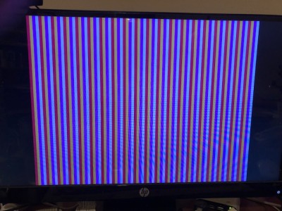
Originally I tried to implement the logic as state machine. Although it worked well in simulation, in real life I could not get it to work, so I settled for this simpler approach which worked pretty well. One more issue bugged me - I saw two horizontal areas on the screen that were considerably darker slowly moving up or down (depending on exact timing used). I tried for almost 2 weeks to figure out why the picture was not stable.

Until I realized that the behavior was very much akin to an acoustic beat https://en.wikipedia.org/wiki/Beat_(acoustics) between the nearly 60Hz picture frequency and 60Hz power. Replacing the power supply with a battery and the error was gone
Attachment:
IMG_0942.jpg
IMG_0942.jpg [ 101.07 KiB | Viewed 999 times ]

_________________
No simulation survives contact with reality!


Top
 Profile  
Reply with quote  
PostPosted: Sun Jan 31, 2021 11:14 am 
Offline
User avatar

Joined: Thu Dec 11, 2008 1:28 pm
Posts: 10943
Location: England
Nice result! It's a good point that the many many LCDs out there have different degrees of flexibility and tolerance. At least you found a way to drive what you have. If at some point you can try with various monitors you might find you need to make some tweaks.

I think the later VGA devices have an I2C facility so the video system can read off what the VGA device is capable of. That's a job for a program, of course, but the hardware would need to be able to do I2C reads. I think bit-banging can do that. But this is probably well out of scope!


Top
 Profile  
Reply with quote  
PostPosted: Sun Jan 31, 2021 1:50 pm 
Offline
User avatar

Joined: Fri Dec 11, 2009 3:50 pm
Posts: 3367
Location: Ontario, Canada
ThePhysicist wrote:
so that was a long break, but when COVID hits your son's daycare suddenly all free time evaporates. At least no one in my family got sick :)
Glad to hear it!

Quote:
At that point my plan to be able to switch between various resolutions vaporized. Looks like modern LCD monitors are not truly multisync, but have a number of fixed frequencies programmed in. I have to stick to standard VGA, and with that in mind using a programmable memory did not make sense anymore. So I decided to do SYNC generation with 2 more GALs and 2 74LS00:
You and other forumites may find it interesting to study this proposed circuit, which requires fewer chips and no programmable logic (only EEPROM's). :)

Quote:
Replacing the power supply with a battery and the error was gone
Congratulations on identifying the problem! And you'll be glad to know there are other solutions besides batteries. Probably your symptom results from a ground loop which can be resolved my reconfiguring the connections between the project, the power supply and the monitor. Have you shared any photos of the project (in another thread, perhaps)?

-- Jeff

_________________
In 1988 my 65C02 got six new registers and 44 new full-speed instructions!
https://laughtonelectronics.com/Arcana/ ... mmary.html


Top
 Profile  
Reply with quote  
PostPosted: Sun Jan 31, 2021 3:07 pm 
Offline

Joined: Wed Jun 17, 2020 10:51 am
Posts: 60
Quote:
Quote:
Replacing the power supply with a battery and the error was gone
Congratulations on identifying the problem! And you'll be glad to know there are other solutions besides batteries. Probably your symptom results from a ground loop which can be resolved my reconfiguring the connections between the project, the power supply and the monitor. Have you shared any photos of the project (in another thread, perhaps)?

If I use a different power supply the problem also disappears. Unfortunately the other power supply is too weak for operation of the whole circuit so the result was dimm and full of instabilities. That's why I tested with strong batteries. My guess - either I will need to put in some large capacitors or use a different power supply.

_________________
No simulation survives contact with reality!


Top
 Profile  
Reply with quote  
PostPosted: Sun Jan 31, 2021 3:09 pm 
Offline

Joined: Wed Jun 17, 2020 10:51 am
Posts: 60
Dr Jefyll wrote:
You and other forumites may find it interesting to study this proposed circuit, which requires fewer chips and no programmable logic (only EEPROM's). :)


nice circuit, thanks

_________________
No simulation survives contact with reality!


Top
 Profile  
Reply with quote  
PostPosted: Sun Jan 31, 2021 3:10 pm 
Offline

Joined: Wed Jun 17, 2020 10:51 am
Posts: 60
BigEd wrote:
Nice result! It's a good point that the many many LCDs out there have different degrees of flexibility and tolerance. At least you found a way to drive what you have. If at some point you can try with various monitors you might find you need to make some tweaks.

I think the later VGA devices have an I2C facility so the video system can read off what the VGA device is capable of. That's a job for a program, of course, but the hardware would need to be able to do I2C reads. I think bit-banging can do that. But this is probably well out of scope!


Good point, but you are right. I2C is really out of scope for the moment!

_________________
No simulation survives contact with reality!


Top
 Profile  
Reply with quote  
PostPosted: Mon Feb 01, 2021 1:19 am 
Offline
User avatar

Joined: Fri Dec 11, 2009 3:50 pm
Posts: 3367
Location: Ontario, Canada
ThePhysicist wrote:
If I use a different power supply the problem also disappears.
By any chance does this different power supply have an AC line cord that's only 2-prong? Whereas the supply that shows interference on screen has 3-prong? If so, the interference may result from a ground loop (assuming the monitor also uses 3-prong).

Otherwise I'd scope the supply's DC output to see if any ripple is present. This interference problem can be solved. Batteries are not the only solution!

_________________
In 1988 my 65C02 got six new registers and 44 new full-speed instructions!
https://laughtonelectronics.com/Arcana/ ... mmary.html


Top
 Profile  
Reply with quote  
PostPosted: Tue Feb 02, 2021 4:20 am 
Offline

Joined: Wed Jun 17, 2020 10:51 am
Posts: 60
both power supplies are 2 pronged and connecting from the same strip. Using an Oszi is on the todo list - as well as trying some big capacitors. You are absolutely right - batteries are not the solution. That was only a quick way to see if the power supply was the problem :)

_________________
No simulation survives contact with reality!


Top
 Profile  
Reply with quote  
PostPosted: Tue Feb 23, 2021 9:14 pm 
Offline

Joined: Wed Jun 17, 2020 10:51 am
Posts: 60
Oszi shows some strange dips of about 0.5V on all signals in line with the image. Putting 470uF capacitors on all small breadboards improved situation, but problem is still noticeable.

After a few changes to the firmware I could generate images out of the Video Ram.
Attachment:
IMG_1028.jpg
IMG_1028.jpg [ 77.26 KiB | Viewed 831 times ]

Here is the schematic
Attachment:
video_card_schematic_v03.pdf [488.76 KiB]
Downloaded 54 times


unfortunately I had to realize that though this works, the solution will not evolve into my final idea. So I riped out all the parts from the breadboards and started from scratch, drawing from the lessons learned so far :)

_________________
No simulation survives contact with reality!


Top
 Profile  
Reply with quote  
PostPosted: Sat Feb 27, 2021 5:36 am 
Offline

Joined: Wed Jun 17, 2020 10:51 am
Posts: 60
Here is a first pass of the new setup:
Attachment:
vga_05_explanation.jpg
vga_05_explanation.jpg [ 208.45 KiB | Viewed 799 times ]

The XY counter generates all the time necessary VGA sync signals. It can also serve as 19bit address counter to either Video Ram. In that case the data from that Video Ram is switched via "Data In" chips onto the 12 bit buffers and send out to the VGA connector.
Alternatively the CPU can get access to either Video Ram. I use a 4kByte window (6 bit x by 6 bit y), augmented by 7 bit of a additional address register to map all 512kbyte into the 6502 address space.

too late today, schematic next time :)

_________________
No simulation survives contact with reality!


Top
 Profile  
Reply with quote  
PostPosted: Sun Feb 28, 2021 7:38 pm 
Offline

Joined: Wed Jun 17, 2020 10:51 am
Posts: 60
Attachment:
vga_05.pdf [568.35 KiB]
Downloaded 49 times

The schematic as promised

_________________
No simulation survives contact with reality!


Top
 Profile  
Reply with quote  
PostPosted: Thu Apr 08, 2021 4:19 am 
Offline

Joined: Wed Jun 17, 2020 10:51 am
Posts: 60
Quick update
Attachment:
IMG_1180.jpg
IMG_1180.jpg [ 128.15 KiB | Viewed 716 times ]

it liiiiiiiives ......

The board is a little bit messy though .....
Attachment:
IMG_1182.jpg
IMG_1182.jpg [ 192.5 KiB | Viewed 716 times ]

And here is the schematics:
Attachment:
vga_v06.pdf [697.1 KiB]
Downloaded 52 times

so next step - I want to add one more feature. A direct connection between both video rams to allow a direct copy of the data in a single frame. If that works out, I'll call it "rev 1 done" and will produce a PCB for it.

_________________
No simulation survives contact with reality!


Top
 Profile  
Reply with quote  
Display posts from previous:  Sort by  
Post new topic Reply to topic  [ 66 posts ]  Go to page Previous  1, 2, 3, 4, 5  Next

All times are UTC


Who is online

Users browsing this forum: No registered users and 10 guests


You cannot post new topics in this forum
You cannot reply to topics in this forum
You cannot edit your posts in this forum
You cannot delete your posts in this forum
You cannot post attachments in this forum

Search for:
Jump to: