Dr Jefyll wrote:
Druzyek, I was looking at the most recent drawing you posted, and (forgive me for saying) it seems a bit hard to comprehend. May I suggest you organize the diagram so most of the signals travel left to right?
Good idea! Thanks for the advice and the example.
Quote:
Have you considered alternatives to the 555 one-shot? It is an analog timer, and maybe it makes more sense to use some sort of digital signal to tell you when the startup sequence is complete. Just an idea.

If there is something cheaper, smaller, or less power consuming, sure. I just need something to give a nice clock edge to switch from writing the memory map to normal operation.
I have been thinking about doing something similar with a microcontroller, which we discussed a little in
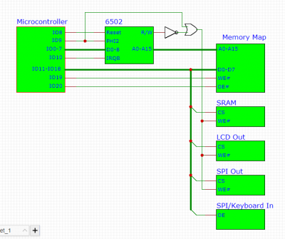
another thread. Here is a simplified version of what I am thinking, which requires a lot less logic.
Attachment:
 6502.PNG [ 27.71 KiB | Viewed 3086 times ]
I could get rid of the NOT and OR here if I could route R/W and clock through the memory map SRAM too, but I'm afraid the garbage coming out before the lines settle could cause inadvertent writes. Maybe if I hook the kind of RAM I'm interested in to an oscilloscope and look at the transitions, I can see if inadvertent writes would be any less likely using some pins than others.
My plan is for the microcontroller to start the 6502 and feed it 0x0000 as the reset vector. Since the microcontroller is not connected to the address lines, it will have to count cycles to know when to provide the address. Starting at 0x0000, the microcontroller writes the CS and OE signals to the memory map (also connected to the address bus) for that address then feeds a NOP to the 6502 to advance the address counter to the next value. After it writes all these values, it feeds more bytes to the 6502 to make it write a small bootloader to load code from the SD card. Then the microcontroller z-states its outputs to the memory map RAM and switches the memory map RAM to output mode, so that it can provide control signals. Last, the microcontroller sets the output pin to the 6502 clock to its own clock (up to 20MHz), z-states its connection to the 6502 data bus, puts itself to sleep and the 6502 runs the bootloader. The microcontroller can wake up from sleep based on a timer and trigger the 6502 interrupt, or the 6502 can wake the microcontroller from sleep by writing to a buffer connected to a microcontroller pin. With more cycle counting, the two chips can exchange data to read timer values, read and write serial, or whatever else the microcontroller can do.
The main hiccup is what the outputs of the 15ns SRAM I would use for the memory map look like when the address lines are settling. If they output data from other addresses while transitioning, it will be fine, but if they output random garbage, all of the peripherals could briefly be put into output mode at the same time, which would be bad.


