Once in a while I feel a little "in over my head" on this project - like right now, for instance. Some parts arrived, and ... good Lord! It's easy to forget how truly tiny an 0603 capacitor is, especially after staring at a large screen for months. Getting an iron between bypass cap and IC pad is going to be very interesting in more than a few places. And there are hundreds of parts and thousands of solder points on these boards!
Well, after my heart-rate came down a bit, I got back to work

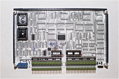
. I printed off scale images of the boards, and, tweezers in hand, I placed a few components - I could easily see various problems. I've circled in red a couple of examples on the pic below, and circled in blue some smaller components that are easy to miss:
Attachment:
 Card A Mockup Marked.jpg [ 550.95 KiB | Viewed 1714 times ]
One issue is that some vias are really quite close to adjacent pads. After Dieter alerted me to it, I opted for covering vias with solder mask to prevent solder bridges. Then I noticed I had a few caps placed WITHIN the outlines of ICs! Silly, but I had the silkscreen layer off when I was placing the caps and just missed it in a few instances. I also underestimated the clearance needed around through-hole IC sockets, and the spacing between bypass caps and nearby pads - it's is just too tight in places. After careful inspection, I think I've spotted most of the trouble spots and will get busy sorting them out as best I can.
Oh, and I also ordered the wrong parts for the inter-card connectors (the pins are too short to reach between the cards

). Aside from that, I'm quite happy really. Considering the many things that could be wrong, it's remarkable that so much is ok. As to how to manage the soldering in really tight spots, well, that remains a mystery. Perhaps solder paste and a heat gun might be the answer, but I guess we'll see how the iron works out first.
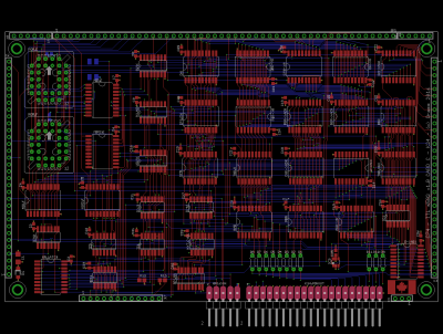
In the meantime, I did a little research on PCB manufacture and discovered "panelizing". Turns out I can put four Eurocards on a single panel and get them made for about the same price as a single card! That's a big deal, and a strong incentive to get the other PCBs done (a good idea anyways just to make sure I don't have any surprises later). Laying out the K24 card was bound to be much easier that the others so I just went for it:
Attachment:
 Card C-K24 Brd.png [ 62.6 KiB | Viewed 1714 times ]
Note the pinout header at bottom for the ADX bus (K24 extended address bus A16..24) and the SPI interface (which follows
Garth's SPI-10 spec 
). The K24 microcode has a custom SPI opcode which should enable the TTL CPU to connect directly to an SPI Mode 3 device on this header.
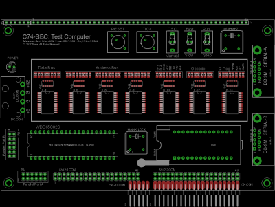
I also decided to try to get a test harness SBC done so I could include it on the PCB panel (the initial testing of the TTL CPU will be with just a memory chip on a breadboard but I'll need an SBC thereafter):
Attachment:
 Card D-SBC Brd.png [ 24.05 KiB | Viewed 1714 times ]
I used
Garth's 6502 Primer,
Daryl's SBC2 and
BDD's POC1 as references here, so the design will look very familiar. The SBC uses a simple variation of Garth's address decoder, an NXP SCC2692 UART per BDD's recommendation, and a WDC65C22 VIA for a nice complement of interrupt sources for testing. I used a 128K RAM chip so the K24 extended address bus can be exercised, and also put the ROM on a ZIF socket to make it easy to re-program. I included a socketed WDC65C02 on the board to let me verify the SBC itself. I can then remove the MPU from it's socket and stack the card on the TLL CPU for testing. Incidentally, I added a wait-state when the SBC accesses peripherals (only when using the FAST clock) so that I can try to run the TTL CPU flat-out and see what happens

. One neat thing is I had some fun implementing the TTL CPU's AUX control signal to switch between FAST and SLOW clocks on the fly. And, of course, I added lots of blinking lights (including some for CPU-internal signals, which will be handy). I'll share the schematics for the SBC shortly.
Ok, that's it for now. Back to those tiny caps

Cheers,
Drass


