cbscpe wrote:
I think you have a serious memory bandwidth problem...
I know, the original plan was for composite video which only needs one byte per PHI2 clock cycle. I'm certainly not willing to sacrifice the '816 CPU time for VGA.
cbscpe wrote:
You need to create a 16-bit data path from RAM to the FPGA.
Let's see if I understand what you're suggesting:
CPU to SRAM, even addresses are used in one SRAM and odd addresses in the other SRAM?
CPLD to SRAM, read 16 bit at once while both SRAM's are selected. How could I select both addresses at the same time while reading with the CPLD?
cbscpe wrote:
I hope you have some pins (you need at least 9) left on the FPGA
I've got 16 unused, and it's actually a CPLD XC95288XL.
cbscpe wrote:
(during PHI1 VGA reads and during PHI2 memory belongs to the CPU)
That's indeed the plan, regardless of choosing to need one or two bytes per PHI2 clock cycle. I'm also considering 16 colors or using composite video. But for now I'd like to understand the 16 bit data path option.
The irony is that I need to write each line twice to get 200 lines per screen. :-/
BigDumbDinosaur wrote:
The use of 55ns RAM is also a limiting factor, as it effectively prohibits clcking the '816 much faster than about 10 Mhz without resorting to wait-stating memory accesses.
I think you're referring to 18.18MHz / 2? During reset the ATMega1284P writes to the SRAM with 14.7456MHz, and reading from it for the VGA happens also at that speed.
To pursue the problem I have with stopping the CPU:
BigEd wrote:
Could you put it into an idle loop and somehow see that it doesn't crash?
I made a simple loop which toggles a VIA pin to visually check if the computer keeps on running.
Dividing the problem into a few smaller ones, I'll first try to halt the system and release it after a given time, and see if the program keeps on running.
BigEd wrote:
Do you have means of diagnosing what happens when the CPU crashes?
with the analyzer I'll monitor A0, D0, PHI2, a VIA pin, RDY and R/W.
I made a 10 bit counter to test with PHI2.
Code:
DCLK = [DIV9..DIV0];
when DIV9 then PHI2 = 1
else PHI2 = DIV3;
This will halt the clock and release it alternatively. I've tested this with the VIA toggle program, which seems to have no problem with it.
Attachment:
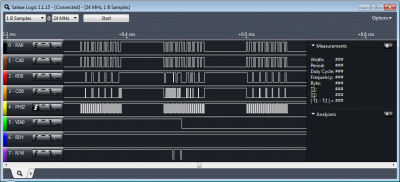 1.png [ 62.56 KiB | Viewed 1139 times ]
Now that it's clear that I don't have to wait three cycles before I can use the bus, I'm trying to halt the system using RDY. RDY is synced with the rising edge of PHI2. However, that works for about two seconds.
Code:
RDY.clk = PHI2;
when DIV9 then RDY := 0
else RDY := 1;
Attachment:
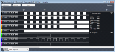 4.png [ 60.42 KiB | Viewed 1139 times ]
What could I try next?


