6502.org Forum  Projects  Code  Documents  Tools  Forum
It is currently Sun Nov 24, 2024 12:04 am

All times are UTC


Post new topic Reply to topic  [ 13 posts ] 
Author Message
 Post subject: Maxim ICM7212 and Code B
PostPosted: Thu Mar 07, 2013 9:36 pm 
Offline

Joined: Mon Apr 16, 2007 6:04 am
Posts: 155
Location: Auckland, New Zealand
Hi all, been a while since I posted here. My last 6502 project was a few years ago but now I am building another little 6502 computer just for fun.

One thing I would like to do is display hex on seven segment LED displays. I was looking around for suitable chips to do this and came across the Maxim ICM7212 (http://www.maximintegrated.com/datasheet/index.mvp/id/1675).

It's a nice little, single chip solution for displaying in hex on a seven segment display.

The interesting thing is there are two variants of the IC, one displays in hex characters and another in this so called 'Code B' where the output, instead of being "0123456789ABCDEF", is "0123456789-EHLP ". Note that is a blank on the end there!

I understand how this all works but I can't find what Code B is actually used for. I posted the question to the EEVBlog forum and got unhelpful replies. I even asked Maxim tech support and they didn't really know either. They did point me at this document http://www.intersil.com/content/dam/Intersil/documents/fn31/fn3159.pdf and in there it says:
"....Code B provides a negative sign (-), a blank (for leading zero blanking), certain useful alpha characters and all numeric formats."

There must be an actual application for this where those particular characters means something though? Or were they just thought up be some engineer who figured they might be useful?

Has anyone here ever actually used this particular output code for anything? Or even heard of it before?

I ordered some samples from Maxim and the ones they do for free are these Code B type. I've ordered things from them before and they've not sent them though so I wonder if they will arrive. My plan was to get the Code B sample one working then the hex version is a drop in replacement.

Simon

_________________
My 6502 related blog: http://www.asciimation.co.nz/bb/category/6502-computer


Top
 Profile  
Reply with quote  
PostPosted: Thu Mar 07, 2013 9:45 pm 
Offline
User avatar

Joined: Fri Aug 30, 2002 1:09 am
Posts: 8546
Location: Southern California
How about an LED driver that lights whatever segments you tell it, meaning it does not have its own character generator. Seven segments isn't enough to do all the letters and characters without some awfully cryptic segment combinations, but it's enough for many of them. At least it would still take care of the strobing so your software doesn't have to babysit it, or have enough outputs (which is more work to wire up) to feed all the segments without strobing. It might also have software brightness control.

_________________
http://WilsonMinesCo.com/ lots of 6502 resources
The "second front page" is http://wilsonminesco.com/links.html .
What's an additional VIA among friends, anyhow?


Top
 Profile  
Reply with quote  
PostPosted: Thu Mar 07, 2013 9:52 pm 
Offline
User avatar

Joined: Tue Nov 16, 2010 8:00 am
Posts: 2353
Location: Gouda, The Netherlands
Does it matter what it was intended for ? It's up to you to decide if you have a use for them. I would consider the hex character version more useful, personally.

Another way to drive seven segment displays is by using a 74HC595 (serial to 8 bit parallel shift register), and hook up the 8 output bits to each digit. That will allow you to arbitrarily select any pattern on the display. By daisy chaining the drivers, you can make a 4 or 8 digit display with only 3 I/O pins.


Top
 Profile  
Reply with quote  
PostPosted: Thu Mar 07, 2013 10:11 pm 
Offline

Joined: Mon Apr 16, 2007 6:04 am
Posts: 155
Location: Auckland, New Zealand
GARTHWILSON wrote:
How about an LED driver that lights whatever segments you tell it, meaning it does not have its own character generator. Seven segments isn't enough to do all the letters and characters without some awfully cryptic segment combinations, but it's enough for many of them. At least it would still take care of the strobing so your software doesn't have to babysit it, or have enough outputs (which is more work to wire up) to feed all the segments without strobing. It might also have software brightness control.


Hi Garth, firstly thanks for your 6502 primer. I've been using t to reacquaint myself with how all this stuff works! I am using part of your address decode scheme in my little machine. Your primer is excellent!

As for the LED thing it is more just for fun I wanted to display HEX values. I would use multiple displays of course, 4 for the address bus and 2 for the data, so I could output the actual values on the bus. It's not actually part of my final machine design. Was more just a tool while building the thing.

What I am going to do though maybe is use an 8 bit latch on the data bus that's addressable in my I/O space and use that as a debug register I can call via code. For debugging I don't mind reading off codes in binary on standard LEDs. I have been playing with the original Woz single step circuit from the Apple 1 to halt the processor and was thinking I could maybe make a hardware breakpoint thing where setting the top bit say halts the processor via the Woz circuit. Then I can see what's on the bus and also single step through the code from that point on. Another debug command in code would reset my status register and clear the break and allow the processor to run freely again.

I don't know if that's feasible but am having fun plodding along trying to find out. I haven't got the single step to work 100% reliably yet though. But it may be since everything is bread boarded with wires all over the place. I seem to be able to stop and start a number of times reliably (say 10 or so) then it will stop and not restart again.

Hi Arlet, you reply came in while I was typing this. No it doesn't matter why really. I am just curious as to why it exists. Someone went to the trouble of inventing a code and actually implementing it in hardware but I can't find any practical, real world application for it so far. The - and (blank) are very useful of course. But the rest seems somewhat arbitrary. I am just curious, that's all. Aren't people curious these days? I guess I am hoping someone will come along and solve the mystery by say 'Ah yes, Code B, we used that on such and such machine back in '79 to display.....'.

I think I have a few 74HC595 so I might try playing with them too. Thanks for the suggestion!

I am just doing all this for fun. Little diversions along the way, finding out about interesting chips and ways of doing things is all part of the fun. That's why this Code B thing intrigues me. It doesn't matter, it's not important, it's just interesting. I might use them just so my computer can say 'HELP'!

Simon

_________________
My 6502 related blog: http://www.asciimation.co.nz/bb/category/6502-computer


Top
 Profile  
Reply with quote  
PostPosted: Sat Mar 09, 2013 5:10 pm 
Offline

Joined: Sun Jan 13, 2013 11:13 am
Posts: 10
Another option for a hex driver for 7 or 14 segment displays is an AVR. Eg: http://saundby.com/electronics/AVR/
There is also the Motorola MC14495, and of course there are 2nd hand TIL-311's around. These are less attractive due to being old stock, and for the TIL-311s they consume a lot of power unless PWM dimmed. The advantage of these though is they contain latches which is handy if you were going to add 74573's or the like. An option if you can find cheap or free stock.


Top
 Profile  
Reply with quote  
PostPosted: Sun Mar 10, 2013 10:28 am 
Offline
User avatar

Joined: Wed Feb 13, 2013 1:38 pm
Posts: 589
Location: Michigan, USA
Speaking of micro-controller based solutions... here's a PIC based two digit design that could be adapted to a four digit address display;

Food for thought. Good luck on your project.

Cheerful regards, Mike

Attachment:
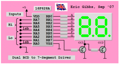
Eric's 4477 IC.PNG
Eric's 4477 IC.PNG [ 23.48 KiB | Viewed 1842 times ]

Attachment:
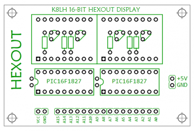
HexOut v0.png
HexOut v0.png [ 31.12 KiB | Viewed 1842 times ]


Code:
;******************************************************************
;                                                                 *
;   Filename: Forum 4477 IC v1.asm                                *
;     Author: Mike McLaren, K8LH                                  *
;       Date: 14-Sep-07  (rev 29-Sep-07)                          *
;                                                                 *
;   8-bit Hex to Dual 7-Segment LED Decoder/Driver IC Firmware    *
;                                                                 *
;   Uses a 16F628A with a 4-MHz INTOSC and Eric Gibbs standard    *
;   multiplexed dual-digit common cathode display circuit         *
;                                                                 *
;   Digit 1 (left) inputs are RA7..RA4 (msb..lsb)                 *
;   Digit 2 (right) inputs are RA3..RA0 (msb..lsb)                *
;   Segments A..G connected to RB0..RB6 via 330 ohm resistors     *
;   Common cathodes connect to RB7 via a 2 transistor circuit     *
;                                                                 *
;      MPLab: 7.40    (tabs=8)                                    *
;      MPAsm: 5.03                                                *
;                                                                 *
;******************************************************************

        #include        <p16f628a.inc>
        errorlevel      -302

        radix   dec

  __config  _MCLRE_OFF & _LVP_OFF & _WDT_OFF & _INTOSC_OSC_NOCLKOUT

;
;  variables
;
digsel  equ     0x21       ; digit select bit b7
delayhi equ     0x22       ; DelayCy() subsystem var'

;==================================================================
;  K8LH DelayCy() subsystem macro generates four instructions     =
;==================================================================
        radix   dec
clock   equ     4               ; 4, 8, 12, 16, 20 (MHz), etc.
usecs   equ     clock/4         ; cycles/microsecond multiplier
msecs   equ     clock/4*1000    ; cycles/millisecond multiplier

DelayCy macro   delay           ; 11..327690 cycle range
        movlw   high((delay-11)/5)+1
        movwf   delayhi
        movlw   low ((delay-11)/5)
        call    uDelay-((delay-11)%5)
        endm

;******************************************************************
;  Reset vector                                                   *
;******************************************************************

        org     0x0000
v_reset
        clrf    STATUS          ; force bank 0                    |B0
;
;  // psuedo C code program example
;
;  char segdata [] = { 0b00111111,      // "0"   -|-|F|E|D|C|B|A
;                      0b00000110,      // "1"   -|-|-|-|-|C|B|-
;                      0b01011011,      // "2"   -|G|-|E|D|-|B|A
;                      0b01001111,      // "3"   -|G|-|-|D|C|B|A
;                      0b01100110,      // "4"   -|G|F|-|-|C|B|-
;                      0b01101101,      // "5"   -|G|F|-|D|C|-|A
;                      0b01111101,      // "6"   -|G|F|E|D|C|-|A
;                      0b00000111,      // "7"   -|-|-|-|-|C|B|A
;                      0b01111111,      // "8"   -|G|F|E|D|C|B|A
;                      0b01101111,      // "9"   -|G|F|-|D|C|B|A
;                      0b01110111,      // "A"   -|G|F|E|-|C|B|A
;                      0b01111100,      // "b"   -|G|F|E|D|C|-|-
;                      0b00111001,      // "C"   -|-|F|E|D|-|-|A
;                      0b01011110,      // "d"   -|G|-|E|D|C|B|-
;                      0b01111001,      // "E"   -|G|F|E|D|-|-|A
;                      0b01110001 };    // "F"   -|G|F|E|-|-|-|A
;
;  void Main()
;  { static unsigned char digsel = 0;   // digit select, 0 or 128
;    cmcon = 7;                         // turn comparator off
;    trisa = 255;                       // Port A all inputs
;    trisb = 0;                         // Port B all outputs
;    while(1)                           // loop forever
;    { unsigned char work = porta;      // sample inputs
;      if(digsel)                       // if left (hi) digit
;        work /= 16;                    // use hi nibble, 0..F
;      else                             // otherwise
;        work &= 15;                    // use lo nibble, 0..F
;      work = segdata[work];            // get segment data
;      work |= digsel;                  // pick up digit select bit
;      portb = work;                    // update display
;      DelayMS(8);                      // ~60 Hz refresh rate
;      digsel ^= 128;                   // toggle digit select bit
;    }                                  //
;  }                                    //
;
        movlw   h'07'           ; turn comparator off             |B0
        movwf   CMCON           ; for digital I/O                 |B0
;
;  setup ports and display sub-system variables
;
        bsf     STATUS,RP0      ; bank 1                          |B1
        movlw   h'FF'           ;                                 |B1
        movwf   TRISA           ; make Port A all inputs          |B1
        clrf    TRISB           ; make Port B all outputs         |B1
        bcf     STATUS,RP0      ; bank 0                          |B0
        clrf    digsel          ; init b7 digit select bit        |B0
;
;  isochronous loop (8-mS, 50% duty cycle, 62.5 Hz refresh rate)
;
Display
        swapf   PORTA,W         ; W = hi nybble in b3..b0 bits    |B0
        btfss   digsel,7        ; left digit? yes, skip, else     |B0
        movf    PORTA,W         ; W = lo nybble in b3..b0 bits    |B0
        andlw   b'00001111'     ; mask off upper 4 bits           |B0
        call    SegData         ; get segment data in W           |B0
        iorwf   digsel,W        ; add digit select bit in b7      |B0
        movwf   PORTB           ; display new digit               |B0
        DelayCy(8*msecs-16)     ; 8-msecs minus 16 cycles         |B0
        movlw   b'10000000'     ; mask for digit select bit       |B0
        xorwf   digsel,F        ; toggle b7 digit select bit      |B0
        goto    Display         ; loop forever                    |B0

;******************************************************************
;  Subroutines                                                    *
;******************************************************************

SegData
        addwf   PCL,F           ;                                 |B0
        retlw   b'00111111'     ; "0"   -|-|F|E|D|C|B|A
        retlw   b'00000110'     ; "1"   -|-|-|-|-|C|B|-
        retlw   b'01011011'     ; "2"   -|G|-|E|D|-|B|A
        retlw   b'01001111'     ; "3"   -|G|-|-|D|C|B|A
        retlw   b'01100110'     ; "4"   -|G|F|-|-|C|B|-
        retlw   b'01101101'     ; "5"   -|G|F|-|D|C|-|A
        retlw   b'01111101'     ; "6"   -|G|F|E|D|C|-|A
        retlw   b'00000111'     ; "7"   -|-|-|-|-|C|B|A
        retlw   b'01111111'     ; "8"   -|G|F|E|D|C|B|A
        retlw   b'01101111'     ; "9"   -|G|F|-|D|C|B|A
        retlw   b'01110111'     ; "A"   -|G|F|E|-|C|B|A
        retlw   b'01111100'     ; "b"   -|G|F|E|D|C|-|-
        retlw   b'00111001'     ; "C"   -|-|F|E|D|-|-|A
        retlw   b'01011110'     ; "d"   -|G|-|E|D|C|B|-
        retlw   b'01111001'     ; "E"   -|G|F|E|D|-|-|A
        retlw   b'01110001'     ; "F"   -|G|F|E|-|-|-|A

;******************************************************************
;  K8LH DelayCy() subsystem 16-bit uDelay subroutine              *
;******************************************************************

        nop                     ; entry for (delay-11)%5 == 4     |B0
        nop                     ; entry for (delay-11)%5 == 3     |B0
        nop                     ; entry for (delay-11)%5 == 2     |B0
        nop                     ; entry for (delay-11)%5 == 1     |B0
uDelay  addlw   -1              ; subtract 5 cycle loop time      |B0
        skpc                    ; borrow? no, skip, else          |B0
        decfsz  delayhi,F       ; done?  yes, skip, else          |B0
        goto    uDelay          ; do another loop                 |B0
        return                  ;                                 |B0

;******************************************************************
        end


Top
 Profile  
Reply with quote  
PostPosted: Wed Mar 13, 2013 12:19 pm 
Offline

Joined: Sat Mar 20, 2010 8:36 pm
Posts: 15
Location: Germany
The EMCO CNC machine uses the 7218 for its display. Main cpu is a 6502. I am afraid that this only used the 'C' version so the data for each digit was loaded, this allowed other characters such as 'S', 'L', etc to be used.


Top
 Profile  
Reply with quote  
PostPosted: Tue Mar 26, 2013 11:59 pm 
Offline

Joined: Mon Apr 16, 2007 6:04 am
Posts: 155
Location: Auckland, New Zealand
Thanks for that. I have some PICs about that would be able to be used for this. I never did receive samples from Maxim but that has happened before. I think NZ people get farmed off to the Asian offices and they don't bother sending anything.

Haven't done much on my project lately as I have been rushing to get another project (car, not computer) ready for this weekend. Hope to be back on 6502 stuff next week.

I did hook a bunch of LEDs to the data bus via a latch which works fine although I spent ages trying to work out why one line was cycling on/off all the time. Eventually I figured out the batch of LEDs I bought from the surplus place contained one flashing one!

Simon

_________________
My 6502 related blog: http://www.asciimation.co.nz/bb/category/6502-computer


Top
 Profile  
Reply with quote  
PostPosted: Wed Mar 27, 2013 12:39 am 
Offline

Joined: Mon Mar 02, 2009 7:27 pm
Posts: 3258
Location: NC, USA
Simon wrote:
...Haven't done much on my project lately as I have been rushing to get another project (car, not computer) ready for this weekend. Hope to be back on 6502 stuff next week...
Simon

Interesting, what are you working on? Also, what kind of vehicle... Maybe post response in the 'Discussion' Thread.
Simon wrote:
...I did hook a bunch of LEDs to the data bus via a latch which works fine...

Simon

Been seeing alot of this lately for some reason. I would highly recommend against using this tactic for testing, even if you use high value resistors... If you must, isolate your 6502 high speed bus with a '244 or something. Even with 1MHz, LEDs are just about useless for diag the databus. I would recommend using a '374 8-bit addressable output port and then only use a high-impedance multimeter set on Volts. The software would change the bits through a large delay...

_________________
65Org16:https://github.com/ElEctric-EyE/verilog-6502


Top
 Profile  
Reply with quote  
PostPosted: Wed Mar 27, 2013 12:50 am 
Offline

Joined: Mon Apr 16, 2007 6:04 am
Posts: 155
Location: Auckland, New Zealand
Well, the 6502 is just a simple general purpose computer. 32k ROM, 16k RAM, CIA, VIA and I also want to add a SID to play with. I want to maybe use it as a simple front end (command line style) to control a RaspPi as a media player. I figure I can output media via HDMI from the Pi but control it all from the 6502 using a CLI interface running in a PIP window on my tellie. There isn't much to discuss about it just yet! Am still bread boarding the basic circuit. I have it running NOPs and the single step (the Woz Apple 1 version) working as well as the address decoding. I just haven't added the RAM and ROM yet.

It's not really meant to be a practical project, just an excuse to make something! I've made a 6502 machine before (Bender's Brain) but that was really just a simplified version of the Commodore 1541 drive circuit reused for something else.

The car is a vintage (well post vintage/pre war) 1937 Austin 7 special. That's all described here (in nauseating detail): http://www.asciimation.co.nz/austin7

Simon

_________________
My 6502 related blog: http://www.asciimation.co.nz/bb/category/6502-computer


Top
 Profile  
Reply with quote  
PostPosted: Mon Apr 01, 2013 6:58 pm 
Offline

Joined: Mon Apr 16, 2012 8:45 pm
Posts: 60
Simon wrote:
this so called 'Code B' where the output, instead of being "0123456789ABCDEF", is "0123456789-EHLP ". Note that is a blank on the end there!

I understand how this all works but I can't find what Code B is actually used for.
Having programmed rather constrained embedded systems I can make a guess.

EHLP is not useful in itself but can be used to spell "HELP". And with "0" doubling as "O" you get "HELLO" as a possibility. "H" and "L" are useful as abbreviations for "High" and "Low". "5" can be read as "S" in words like "SLO", "SHELL", "SPELL", or meaning perhaps "Store" with "L" corresponding to "Load". Likewise "8" can be read as "B" so you cab spell "BELL".

To get it all you will have to permute OISB-EHPL and match against a dictionary to get all possible words. Sounds like a typical Unix script job. The character set looks like the result of inventiveness overcoming constraints.


Top
 Profile  
Reply with quote  
PostPosted: Tue Apr 02, 2013 4:52 am 
Offline

Joined: Mon Jan 07, 2013 2:42 pm
Posts: 576
Location: Just outside Berlin, Germany
Wouldn't it make more sense to use an EEPROM with tables of possible combinations to drive a seven-segment display? Sure, you'd be wasting lots of memory, but they're inexpensive, and there is no micro-controller to program.


Top
 Profile  
Reply with quote  
PostPosted: Tue Apr 02, 2013 11:42 am 
Offline

Joined: Fri Nov 26, 2010 6:03 pm
Posts: 46
Location: NSW, Australia
Quote:
To get it all you will have to permute OISB-EHPL and match against a dictionary to get all possible words. Sounds like a typical Unix script job.

Code:
$ egrep ^[oilsgehlp]+\$ /usr/share/dict/web2


Top
 Profile  
Reply with quote  
Display posts from previous:  Sort by  
Post new topic Reply to topic  [ 13 posts ] 

All times are UTC


Who is online

Users browsing this forum: No registered users and 69 guests


You cannot post new topics in this forum
You cannot reply to topics in this forum
You cannot edit your posts in this forum
You cannot delete your posts in this forum
You cannot post attachments in this forum

Search for:
Jump to: