Trivial circuits for sbc
-
Nightmaretony
- In Memoriam
- Posts: 618
- Joined: 27 Jun 2003
- Location: Meadowbrook
- Contact:

Nightmaretony wrote:
Now replace the NMOS 6502 with a 65C02 and watch your heat and power issues disappear in addition to a whole slew of advantages. Made the switch years ago, I wont go back....
Here i found some useful comparisons for logic ic:
http://www.kpsec.freeuk.com/components/ic.htm#logic
I bought the TL7705 ic, for the reset circuit like on André's Gecko schematic. I hope it will solve the reset circuit issue.
(A bit off topic) Anyway, every ic that i have is in the 0 to 70c range, and i had built a pic based clock(with lots of other ic inside), an one day i was curious, and i left it in the freezer on -5,-10c i don't know exactly how much, for an hour. The clock worked as usual, so what is the problem with low temperatures and regular ic?
(A bit off topic) Anyway, every ic that i have is in the 0 to 70c range, and i had built a pic based clock(with lots of other ic inside), an one day i was curious, and i left it in the freezer on -5,-10c i don't know exactly how much, for an hour. The clock worked as usual, so what is the problem with low temperatures and regular ic?
-
GARTHWILSON

- Forum Moderator
- Posts: 8774
- Joined: 30 Aug 2002
- Location: Southern California
- Contact:
I can't remember for sure, but it seems like it was not a matter of it not working at all but rather that it may no longer meet the specifications for leakage, output drive, and things like that. OTOH, at the high-temperature end, parts will slow down and may not meet the timing spec.s. Again it doesn't mean they suddenly stop working, but they're no longer guaranteed to meet the specifications.
GARTHWILSON wrote:
I can't remember for sure, but it seems like it was not a matter of it not working at all but rather that it may no longer meet the specifications for leakage, output drive, and things like that. OTOH, at the high-temperature end, parts will slow down and may not meet the timing spec.s. Again it doesn't mean they suddenly stop working, but they're no longer guaranteed to meet the specifications.
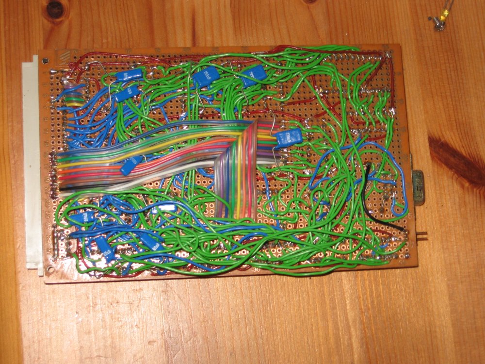
I started soldering my 68000 sbc, because i need to finish it by the end of the semester. Here is the picture of what i've done so far.
(I've only started soldering...)
Now, i've seen in other topics some issues with wires not going straight, now i was wondering if this looks like the case. Will there be some problems with the sbc if the wires are packed close and going into 90 degrees turns? Or should i make it more like a ball of wire(loose wires)?
(Sorry if it is not the 6502 i don't know any other forum that might help with this kind of hardware question, this question would also apply for 65xx based sbc.)
-
GARTHWILSON
- Forum Moderator
- Posts: 8774
- Joined: 30 Aug 2002
- Location: Southern California
- Contact:
I've found a couple of problems in that kind of wiring in my own experience.
- One is that after a lot of wires are down, they have to keep getting moved to solder to more pins that got covered up, and all the moving tends to break the wires right at the end of the insulation, or where they are soldered.
- The other problem is that it's hard to solder more than one or two wires to a pin.
- It lets you put many wires on one pin, even after the pin is surrounded with lots of other wire "traffic" going past it.
- Wires have no tendency to break. (Part of the job is wraping a little of the insulated portion onto the pin. After the first level, subsequent ones can have their insulated portion wound over a previous wrap, so this does not take up any more pin length.)
- You can get shorter, straighter connections, without preventing more connections from being made later.
- What the newcomer may not realize is that WW is totally reliable, even though you don't solder. If the posts are clean, and you strip the wire immediately before wrapping it and do not touch the wire (we don't want skin oils on it), you will get a reliable chemical weld where the corners of the post bite into the wire. If you unwrap an erroneous wrap, you can actually feel these tiny welds breaking if you have a careful touch.
- WW allows greater density and therefore shorter connections, as you can put the sockets shoulder to shoulder on the board, with no room between them, and still have no problem connecting everything.
Using wires like that can work out. I built a whole computer with this technique: http://www.6502.org/users/andre/csa/gallery/index.html or the video card: http://www.6502.org/users/andre/csa/vdc/csavdcflip.jpg
And this computer worked up to 2 MHz. There is a saying in this forum: "with 1MHz you can get away with (the proverbial) murder".
However, you have to be good with your soldering skills, as you have to connect multiple wires in a single joint. I found I could do some better layouting this way, but as Garth mentioned, then wires need to be moved to the side while debugging and yes, they do break. You do cover up older wires with newer ones, build some kind of layering. So you should be very confident about your schematics, and double check everything to avoid having to cut them because you have fix something a layer deeper.
I've never done wire wrapping, so I cannot comment on that. Once I had the money I started getting the boards produced, which makes it so much easier, and I can also better publish this on the web so others can build it again...
But for your problem and your question... this really looks like how I started :-)
1) do not forget the bypass caps between VCC and GND for each chip. I see you've started with the power grid, I suggest do them next. I only used NMOS in the beginning, which does not produce as many noise, CMOS is much more susceptible to that.
2) Use thicker/stronger wires for power supply. If you're not doing a star-connect (which is most likely not necessary for low frequencies), make a network (e.g. connect GND from the left row and right row of ICs at regular intervals. Make additional wires from the power supply to the other side of the board (mimicking a star-network) if you can't use thicker wires (or don't want to replace the ones you soldered already)
3) when a wire is soldered to a pin, and it has high frequencies on it, make sure the tip of the wire does not protrude close to the pin next to it. I had some cross-talk on my video board that I fixed by cutting the wire tip close to the soldering joint. So basically make sure you have enough spacing between signals.
4) I haven't used it but looking at the discussion about pcb design I'd suggest for high frequency signals to pair it with a GND wire. For example if you have an 8 or 16MHz signal to cross the PCB, use two connected wires, one for the signal and one for GND. That should capture some interference.
5) As mentioned above, plan ahead what you want/have to solder when. wires can be buried under layers of other wires and it is then sometimes difficult to change them. Double check everything.
That's what comes to mind right now. I hope it helps
André
Finally i got the scope Hameg HM 512, and i managed to get the mc68000 sbc in working condition(@4MHz, i will increase it to 8), for now it just counts number in a infinite loop, and stores some random values at some address, it is just a test program. Anyway i hook it to the scope, and the is some crosstalk on the buses, but it seems that the system is not affected. I could try to add some dummy grounded wires in that mess to adsorb some crosstalk...
As for the soldering mess, it is kinda inevitable, but ti should not be too much of a problem if i make a good plan for the wiring...
As for the soldering mess, it is kinda inevitable, but ti should not be too much of a problem if i make a good plan for the wiring...
I didn't want to open a new topic for this, but there is a small lottery on www.sparkfun.com, they offer 100$ shopping reward!
It is over
I tried for 4 hours but nothing.
It is over
I tried for 4 hours but nothing.
Anyway, last week i finally installed the TL7705 ic as my reset circuit.
Well, like always i turned on my soldering station, soldered the ic, but i didn't turned off the solder before i tested it, in case i did something wrong. The circuit worked on it's first test, so i went to turn off my soldering station, and when i flipped the switch the sbc restarted. I was surprised, so i toggled the switch a few more times, and every time a spark occurred in the switch the TL7705 would send a restart signal. It seems that the TL7705 really works, and it seems to detect power spikes, but that might also mean that the sbc power wiring is far from ideal...
Well, like always i turned on my soldering station, soldered the ic, but i didn't turned off the solder before i tested it, in case i did something wrong. The circuit worked on it's first test, so i went to turn off my soldering station, and when i flipped the switch the sbc restarted. I was surprised, so i toggled the switch a few more times, and every time a spark occurred in the switch the TL7705 would send a restart signal. It seems that the TL7705 really works, and it seems to detect power spikes, but that might also mean that the sbc power wiring is far from ideal...
As for my power supply, i am planning to use a custom made 10V ,20W transformer(from a local manufacturer) and a voltage regulator(7805+2N3055). I've already made something similar with my 68k sbc, and it works fine, but now i was wondering how will the proximity of the power transformer affect the sbc(since they will share the same housing). Will it work just fine, or will it cause interference? I've made a small experiment, i took another similar transformer and i placed it close to the sbc(running @230V of course). The sbc was running a small program in EhBasic, without any difficulties.
As for the atx, i don't have any, and they kinda wouldn't fit in the housing.
Edit: Looking at the Altair 8800, it had a huge transformer just behind the circuit boards...
As for the atx, i don't have any, and they kinda wouldn't fit in the housing.
Edit: Looking at the Altair 8800, it had a huge transformer just behind the circuit boards...
-
BigDumbDinosaur

- Posts: 9427
- Joined: 28 May 2009
- Location: Midwestern USA (JB Pritzker’s dystopia)
- Contact:
Watch out for them shorts!
Dajgoro wrote:
...now i was wondering how will the proximity of the power transformer affect the sbc(since they will share the same housing). Will it work just fine, or will it cause interference?
The trouble with your plan to use a linear power supply is the lack of crowbar capability in case something goes to ground. The 7805 regulator will current-limit if subjected to a direct short but may not respond to a low resistance fault (unless >1.1 amps is drawn). I'd think about this some more if I were you. You can get inexpensive switching power supplies in bare board form that will provide what you need, along with crowbar capability.
x86? We ain't got no x86. We don't NEED no stinking x86!
-
GARTHWILSON
- Forum Moderator
- Posts: 8774
- Joined: 30 Aug 2002
- Location: Southern California
- Contact:
Having the transformer close won't be any problem. The magnetic field is pretty well contained in a closed loop in its core. Power transformers are routinely used in audio equipment that has to have a very low noise floor. Where you have to be more careful in design and construction is keeping digital noise out of analog circuits.
http://WilsonMinesCo.com/ lots of 6502 resources
The "second front page" is http://wilsonminesco.com/links.html .
What's an additional VIA among friends, anyhow?
The "second front page" is http://wilsonminesco.com/links.html .
What's an additional VIA among friends, anyhow?
Re: Watch out for them shorts!
BigDumbDinosaur wrote:
Dajgoro wrote:
...now i was wondering how will the proximity of the power transformer affect the sbc(since they will share the same housing). Will it work just fine, or will it cause interference?
The trouble with your plan to use a linear power supply is the lack of crowbar capability in case something goes to ground. The 7805 regulator will current-limit if subjected to a direct short but may not respond to a low resistance fault (unless >1.1 amps is drawn). I'd think about this some more if I were you. You can get inexpensive switching power supplies in bare board form that will provide what you need, along with crowbar capability.