Adam (1) describes a clock circuit originating from Harry the Bastard, who can no longer be found.
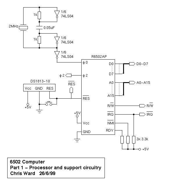
Chris Ward shows an identical circuit (2).
Thomas Scherrer (3) shows a similar circuit with different values and a ground connection through a capacitor.
Q1. Adam refers to a '6502' and uses a 2MHz crystal. My CPU is marked R6502P, which is rated at 1 MHz. What should I change?
Q2. Should it work without the ground connection? What is the benefit?
Q3. Adam suggests a "... need to play around ...", particularly with crystal frequency and capacitor rating. How different a capacitance do I need to try? (I shall have to go online to find these, so your guidance will save me time).
Many thanks, Robin
(1) http://www.reocities.com/SiliconValley/ ... 02prj1.htm
(2) http://www.chrisward.org.uk/6502/schematics/6502-1.png
(3) http://www.gaby.de/z80/uexosc.htm
Newbie clock help

Welcome!
The best advice seems to be to use an oscillator instead of a crystal, unless you have a particular reason.
See here and for example this part.
We had some fun with crystal circuits here too with a Micro UK101 kit, but at 8MHz not 1MHz (that computer divides down a higher frequency)
Cheers
Ed
Edit: A few pages of Harry the Bastard survive on archive.org, but nothing too specific about clocking.
Also, this page might help a little if experimenting with that classic oscillator circuit.
(Edits to fixup links)
Last edited by BigEd on Mon Sep 03, 2018 5:48 am, edited 5 times in total.

For frequencies that are not greater than few MHz, it is possible to use a 4060 counter, as it has the possibility to be rigged as a oscillator with very few components(the schematic can be found in the datasheet, and here: http://www.instructables.com/id/Two-chi ... scillator/). I usually would use the 4060 only as a oscillator, and take its output to some other counter so i can have lower frequencies too... Also once i used it with a 32.768KHz crystal to get a 2Hz clock for my digital clock project.
I've used the second circuit at this link which works perfectly well.
Edit: seems to return the same content as your link (3).
My CPU is a 2MHz device so I routed the resulting waveform into the clock input of a d-type flipflop with the negated output tied to the d input.
That gives you half the input clock frequency.
If you want half that again (1MHz) then use the other half of the TTL device (74LS74) and you will obtain a 1MHz clock for your CPU.
Note: Using a 4MHz crystal.