6502.org Forum  Projects  Code  Documents  Tools  Forum
It is currently Sun Nov 24, 2024 3:21 pm

All times are UTC


Post new topic Reply to topic  [ 102 posts ]  Go to page Previous  1 ... 3, 4, 5, 6, 7
Author Message
PostPosted: Fri Jan 19, 2024 12:25 am 
Offline
User avatar

Joined: Fri Dec 11, 2009 3:50 pm
Posts: 3367
Location: Ontario, Canada
BigDumbDinosaur wrote:
For a first effort, I’d suggest you find a 6551 [...] The bus interface will be much easier
A lot depends on circumstances. If being able to use the chip that's already in your possession is a fairly high priority for you, bogrol, then perhaps you won't mind if its interface for 65xx isn't the simplest. The amount of extra logic required is actually fairly small.

This edited version of Figure 4 from the datasheet could use a second set of eyes but it ought to steer you in the right direction. (I'm drawing attention to generation of the MR, /DISTR and /DOSTR signals, which are the ones that present the obvious challenge.)

Can you tell us more about your 6502 SBC, bogrol? Perhaps it already has the /RD and /WR signals shown in my diagram, as that's what is sometimes used to drive /OE and /WR on the RAM chip. And what's the clock rate?

-- Jeff

ps- welcome!


Attachments:
8250 bus logic.png
8250 bus logic.png [ 36.94 KiB | Viewed 2907 times ]

_________________
In 1988 my 65C02 got six new registers and 44 new full-speed instructions!
https://laughtonelectronics.com/Arcana/ ... mmary.html
Top
 Profile  
Reply with quote  
PostPosted: Fri Jan 19, 2024 12:59 am 
Offline

Joined: Fri Dec 21, 2018 1:05 am
Posts: 1120
Location: Albuquerque NM USA
In a pinch, you don't need a dedicated serial device; you can bit bang serial port with a buffer and latch.
Bill


Top
 Profile  
Reply with quote  
PostPosted: Fri Jan 19, 2024 4:25 am 
Offline

Joined: Thu Jan 18, 2024 6:50 pm
Posts: 4
Location: Hungary
Dr Jefyll wrote:
BigDumbDinosaur wrote:
For a first effort, I’d suggest you find a 6551 [...] The bus interface will be much easier
A lot depends on circumstances. If being able to use the chip that's already in your possession is a fairly high priority for you, bogrol, then perhaps you won't mind if its interface for 65xx isn't the simplest. The amount of extra logic required is actually fairly small.

Yes, it would be best to use what I have now even if it means I have to add some more glue logic, I'm more than willing to learn. :)

Dr Jefyll wrote:
This edited version of Figure 4 from the datasheet could use a second set of eyes but it ought to steer you in the right direction. (I'm drawing attention to generation of the MR, /DISTR and /DOSTR signals, which are the ones that present the obvious challenge.)

Can you tell us more about your 6502 SBC, bogrol? Perhaps it already has the /RD and /WR signals shown in my diagram, as that's what is sometimes used to drive /OE and /WR on the RAM chip. And what's the clock rate?

Very well. I'm using Garth's decoding design and a NOT-gate (from NANDs) crystal oscillator (giving 1.8432MHz) The rest of it is the same as the simplified version of Garth's schematics by Ben Eater, the VIA is mapped by A13.

It is evident that MR is wired throught a NOT. On the datasheet scheme you linked, are the triangles to the right also NOTs? Or diodes and then are they necessary? I have also found the 8250-compatible design of the Zeta SBC being worth a look at as it uses a Z80 MPU.

bogrol wrote:
- WR active low (pin 18) to 5V, active high (pin 19) to R/W
- RD active low (pin 21) to R/W, active high (pin 22) to GND

The R/W signal I'm referring to is the one directly from the 6502.

Ps. I'm out of board space for a port built with discrete parts as suggested by plasmo.

Dr Jefyll wrote:
-- Jeff

ps- welcome!


Top
 Profile  
Reply with quote  
PostPosted: Fri Jan 19, 2024 6:21 am 
Offline
User avatar

Joined: Fri Dec 11, 2009 3:50 pm
Posts: 3367
Location: Ontario, Canada
bogrol wrote:
The rest of it is the same as the simplified version of Garth's schematics by Ben Eater, the VIA is mapped by A13.
I'm not familiar with this, so a link to Ben's version would be helpful. And indeed, I suggest you make a schematic diagram of your own version... of Ben's version of Garth's version! :lol:

Seriously, I recommend you have an actual diagram of your own project. That's because it will end up being unique (what with the 8250 and other details). It's much less error-prone to have all the information in one place (as compared with looking at someone else's diagram, while meanwhile trying to remember how you own version differs).

Quote:
On the datasheet scheme you linked, are the triangles to the right also NOTs?
No, those are sections of a 1488 IC and sections of a 1489 IC. Their job is to convert the voltage levels of incoming and outgoing signals, because it's sometimes the case that you'll want +/- 12V levels... or not, depending on what sort of device attaches to the other end of your serial connection. BTW, modern equivalent ICs are preferable in some ways to the venerable 1488 and 1489.
Attachment:
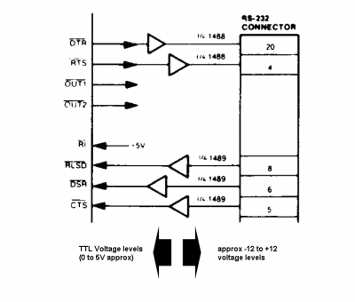
voltage levels.png
voltage levels.png [ 39.9 KiB | Viewed 2887 times ]


bogrol wrote:
bogrol wrote:
- WR active low (pin 18) to 5V, active high (pin 19) to R/W
- RD active low (pin 21) to R/W, active high (pin 22) to GND

The R/W signal I'm referring to is the one directly from the 6502.
This won't work, I'm afraid. And BTW trying to EXPLAIN connections can get quite confusing. :roll: A diagram (as I suggested) is much better.

Quote:
Ps. I'm out of board space for a port built with discrete parts as suggested by plasmo.
Hmm, but didn't you mention a VIA? :) You could use one of the VIA's ports for plasmo's suggestion...

-- Jeff

_________________
In 1988 my 65C02 got six new registers and 44 new full-speed instructions!
https://laughtonelectronics.com/Arcana/ ... mmary.html


Top
 Profile  
Reply with quote  
PostPosted: Fri Jan 19, 2024 8:05 am 
Offline

Joined: Thu Jan 18, 2024 6:50 pm
Posts: 4
Location: Hungary
Here your go, I hope it's adequate. I have two clocks, one 1MHz driving the CPU and other things and one 1.8432MHz for the UART. As the CPU wants to read from the UART, R/W becomes HIGH and thus UART pin 22 (DISTR) is active. When writing, R/W is LOW and such DOSTR becomes active.


Attachments:
6502_8250.pdf [252.2 KiB]
Downloaded 62 times
Top
 Profile  
Reply with quote  
PostPosted: Fri Jan 19, 2024 8:27 am 
Offline
User avatar

Joined: Fri Dec 11, 2009 3:50 pm
Posts: 3367
Location: Ontario, Canada
bogrol wrote:
As the CPU wants to read from the UART, R/W becomes HIGH and thus UART pin 22 (DISTR) is active. When writing, R/W is LOW and such DOSTR becomes active.
I agree, but this doesn't satisfy the timing requirements shown in Figure 11 and Figure 12 of the datasheet (page 17). The DISTR and DOSTR signals aren't supposed to go active until after the address lines have settled -- see the tDIC and tDOC parameters shown in the figures. That's why in my suggested circuit I have used PHI2 to qualify DISTR and DOSTR (actually /DISTR and /DOSTR).

You can be confident the address lines from the CPU will be stable by the time PHI2 goes high. But at other times the address lines may be in transition, and it can cause trouble if DISTR and DOSTR are active.

-- Jeff

_________________
In 1988 my 65C02 got six new registers and 44 new full-speed instructions!
https://laughtonelectronics.com/Arcana/ ... mmary.html


Last edited by Dr Jefyll on Fri Jan 19, 2024 8:37 am, edited 1 time in total.

Top
 Profile  
Reply with quote  
PostPosted: Fri Jan 19, 2024 8:36 am 
Offline

Joined: Thu Jan 18, 2024 6:50 pm
Posts: 4
Location: Hungary
Ah, very insighful, thanks! Do you think replicating this would suffice then or is it more complicated? I'll write a little program then to test it. Slim chances but we'll see.

Also worried about the lines on the right, particularly the CSOUT. As I understand it is merely an indicator to the other party?


Attachments:
Capture.PNG
Capture.PNG [ 1.52 KiB | Viewed 2865 times ]
Top
 Profile  
Reply with quote  
PostPosted: Fri Jan 19, 2024 8:43 am 
Offline
User avatar

Joined: Fri Dec 11, 2009 3:50 pm
Posts: 3367
Location: Ontario, Canada
bogrol wrote:
Do you think replicating this would suffice
Yeah, it should. And really there's no great insight involved. This sort of approach is extremely common, because with virtually all microprocessors it's normal for the address bus to be unreliable for a brief period as one cycle ends and the next begins. So, you need the peripheral device to "stop paying attention" during this time.

-- Jeff

_________________
In 1988 my 65C02 got six new registers and 44 new full-speed instructions!
https://laughtonelectronics.com/Arcana/ ... mmary.html


Top
 Profile  
Reply with quote  
PostPosted: Fri Jan 19, 2024 9:06 am 
Offline
User avatar

Joined: Fri Aug 30, 2002 1:09 am
Posts: 8546
Location: Southern California
Your last diagram needs some input labeling, and then it will probably be correct.  It should look like the one near the bottom of the clock-generation page of the 6502 primer, at http://wilsonminesco.com/6502primer/ClkGen.html .

_________________
http://WilsonMinesCo.com/ lots of 6502 resources
The "second front page" is http://wilsonminesco.com/links.html .
What's an additional VIA among friends, anyhow?


Top
 Profile  
Reply with quote  
 Post subject: Re:
PostPosted: Sat Feb 03, 2024 3:14 pm 
Offline

Joined: Wed Aug 21, 2019 6:10 pm
Posts: 217
Dajgoro wrote:
Well, i wanted to be able to connect my project to any computer, so i bought this from ebay:
http://www.ebay.com/itm/CP2102-Module-Serial-Converter-USB-2-0-TTL-UART-6PIN-/250872278843?pt=LH_DefaultDomain_0&hash=item3a69272f3b

Usb to ttl module, but i if i got it right this module does not have any clock input or output, how do i connect it the to the 6850(or elsewhere)???


You connect it to the Tx Data and Rx Data lines (pins 2 & 6) for a two wire UART serial interface.

UART / RS232C do not include a clock in the interface, which is why the two sides have to agree on how fast they are sending and receiving data. So if you look in the Motorola MC6850 datasheet expanded block diagram (figure 9 in the one I am looking at), you will see that the Tx Clock and Rx Clock pins are not outputs, they are inputs.

In UART interfaces that support hardware flow control, you may also connect CTS and DTS (pins 5 & 24) for a four wire serial UART interface, but the TTL/USB adapter you cite doesn't have CTS/DTS lines. The other four lines of that adapter are +3.3V, +5v, GND, and /Reset.


Top
 Profile  
Reply with quote  
PostPosted: Sat Feb 03, 2024 3:38 pm 
Offline
User avatar

Joined: Thu Dec 11, 2008 1:28 pm
Posts: 10986
Location: England
I think that query was already resolved back in 2012!
viewtopic.php?p=18706#p18706

Edit: I see you must have landed at the bottom of page 1 and not noticed the thread continued for pages and years... we've all done it!


Top
 Profile  
Reply with quote  
PostPosted: Sun Feb 04, 2024 7:37 am 
Offline

Joined: Wed Aug 21, 2019 6:10 pm
Posts: 217
BigEd wrote:
I think that query was already resolved back in 2012!
viewtopic.php?p=18706#p18706

Edit: I see you must have landed at the bottom of page 1 and not noticed the thread continued for pages and years... we've all done it!


That's exactly what happened ... the morning sun was coming in the window and playing games with my cataracts.


Top
 Profile  
Reply with quote  
Display posts from previous:  Sort by  
Post new topic Reply to topic  [ 102 posts ]  Go to page Previous  1 ... 3, 4, 5, 6, 7

All times are UTC


Who is online

Users browsing this forum: No registered users and 29 guests


You cannot post new topics in this forum
You cannot reply to topics in this forum
You cannot edit your posts in this forum
You cannot delete your posts in this forum
You cannot post attachments in this forum

Search for:
Jump to: