akohlbecker wrote:
Why would a bank address of 0 be safer than any other value during power up?
Also, a 273 is not recommended because it is a D flip flop, meaning the bank address only appears after the clock rising edge. You want a transparent latch so the bank address is already present, and the select logic has already propagated, before the clock rises! That's important for WDC I/O chips for example.
This is a great point, I haven't thought about it.
akohlbecker wrote:
Really the circuit shown in the datasheet for demultiplexing the bank address is all you need, unless you want to use BE or RDY. For the latter I go into it in more detail in episodes 3, 5 and 6 of my YouTube series.
Somehow, I missed that page! Good to know the recommended solution.
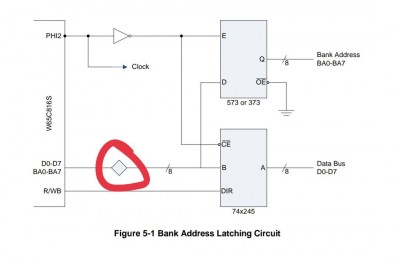
EDIT: In the datasheet, on the page with address demux curcuit, what does the square rotated by 45° mean? Is it some sort of buffer?
Attachment:
 IMG_20230901_230559_272.jpg [ 36.65 KiB | Viewed 4201 times ]
drogon wrote:
Just to add another data-point:
In my ruby 816 system, I use a GAL to latch the upper N address bits and no separate data bus buffer. Works for me, but I only have one peripheral - a 65C22 and simple address decoding done in another GAL to allow for 512KB of RAM and the VIA.
-Gordon
Are there any benefits of using a GAL instead of a 74xx latch?
_________________
/Andrew
deck65 - 6502 slab with screen and keyboard |
ПК-88 - SBC based on KM1810VM88 (Ukrainian i8088 clone) |
leo80 - simple Z80 SBC
nice65 - 6502 assembly linter |
My parts, footprints & 3D models for KiCad/FreeCAD


