6502.org Forum  Projects  Code  Documents  Tools  Forum
It is currently Wed May 15, 2024 1:27 pm

All times are UTC


Post new topic Reply to topic  [ 67 posts ]  Go to page Previous  1, 2, 3, 4, 5  Next
Author Message
PostPosted: Fri Jun 30, 2023 3:19 pm 
Offline

Joined: Fri Mar 18, 2022 6:33 pm
Posts: 443
sburrow wrote:
I have ONE breadboard, and if I *look* at it the wrong way it freaks out. I even got the breadboard brand that Ben Eater suggested! I even cut my own 22 gauge wires! AND THEY ARE SOLID COPPER!
I have quite a few of those BusBoard breadboards. They are not bad, but they're not my favorites any more. I find they work well at first, but wear out quickly. They're good for what Ben uses them for (making nice looking demo boards for YouTube videos) but not so good for experimenting when you're constantly ripping wires out and redoing things.

You might be interested in Radical Brad's page on breadboarding technique: https://www.atomiczombie.com/vulcan-74-page-1/

Incidentally, this is another reason I'm moving away from the BusBoard breadboards. I have a big stack of ethernet cable with 23 AWG wire. The jaws of the clips in the BusBoard breadboards are just a little too soft to reliably use the thinner wire. Depending on where you buy them, the Twin Industries ones that Radical Brad uses are a dollar or so cheaper than the BusBoard ones too. I think Mouser has them for $6.99.

Edit: Here's a side-by-side of my older array of BusBoard breadboards, along with my newer Twin Industries ones (the blueish ones). I went ahead and paid a dollar or two more for the "high temperature" breadboards, not because I'm planning to operate at high temperatures, but because I really like the round holes. Internet articles about breadboards say that round vs. square holes is just personal preference and makes no difference in how the wires insert. I don't find that to be true; the round "dimples" tend to guide the wire to exactly the right spot over the jaws of the clip, whereas with the square ones the wires tend to get caught in the corners and on the edges of the hole. Another good feature of these boards is the actual openings of the holes themselves are much smaller - only a little bit wider than the wires. This means that even with narrower 23 AWG wire the insulation won't "fall through" and interfere with the clips. You can push the wire in until it stops, with the insulation resting on the plastic and the wire firmly seated in the jaws of the clip.
Attachment:
20230630_115407.jpg
20230630_115407.jpg [ 4.21 MiB | Viewed 458 times ]


Quote:
Well, you say that now. "Just add more RAM". I will say that every bit of color or resolution you add will make the system harder to handle. Sometimes in more subtle ways. Video circuits have been my primary focus for the past (almost) two years now, and I am still learning the physical limitations.

For example, you want color text, so what data are you sending through this dual-port RAM? Are you sending the character value and then it's color value? Or do you limit it's character value potential to add more color options? If you switch from monochrome, it seems you would need extra instructions to send the pertinent color info and still have it display correctly.
How I would do it, conceptually, is with parallel RAM. I would scan the color buffer exactly the same way I scan the frame buffer. So every 8 pixels there would be a LOAD event; the shift register would get the next 8 dots from the character rom, and the color latch would get the next byte of color data. The color latch would drive the RGB lines of the monitor and the shift register would just enable / disable the color latch's outputs. This would take up another 2k+ of address space, which is certainly doable, but I wanted to keep things simple. Colorful output isn't really important to the aesthetic I'm going for (kind of late 70s early 80s "Alien").

_________________
"The key is not to let the hardware sense any fear." - Radical Brad


Top
 Profile  
Reply with quote  
PostPosted: Fri Jun 30, 2023 7:44 pm 
Offline
User avatar

Joined: Thu May 28, 2009 9:46 pm
Posts: 8183
Location: Midwestern USA
Paganini wrote:
BigDumbDinosaur wrote:
I doubt it, unless all outputs are loaded to where they have to deliver significant current. That wouldn’t be the case if an output is driving a CMOS input, unless a lot of parasitic capacitance is present.

It's on a breadboard; might that be enough parasitic capacitance?

Dunno. Breadboard setups seem to have more trouble with inductance in those long wires than capacitance.

_________________
x86?  We ain't got no x86.  We don't NEED no stinking x86!


Top
 Profile  
Reply with quote  
PostPosted: Sun Jul 02, 2023 10:57 pm 
Offline

Joined: Fri Mar 18, 2022 6:33 pm
Posts: 443
Current state of the project:
Attachment:
20230702_184809.jpg
20230702_184809.jpg [ 4.19 MiB | Viewed 408 times ]


And the output:
Attachment:
20230702_184750.jpg
20230702_184750.jpg [ 4.51 MiB | Viewed 408 times ]


This is the big ASUS monitor that I have nicknamed "Fussy." Last time I did all my testing on a nice old IBM monitor I have. When I thought I had everything ironed out I plugged "Fussy" in and it complained mightily. This is the first time I've had the output this clean and stable on "Fussy." However, there is one consternating problem: there are only 79 columns! What happened to the last one? I don't know... I must have made some kind of basic math error someplace. :x

_________________
"The key is not to let the hardware sense any fear." - Radical Brad


Top
 Profile  
Reply with quote  
PostPosted: Mon Jul 03, 2023 3:37 am 
Offline
User avatar

Joined: Tue Feb 28, 2023 11:39 pm
Posts: 146
Location: Texas
Paganini wrote:
I must have made some kind of basic math error someplace. :x


The two hardest problems in Computer Science are caching and off by one errors. :mrgreen:


Top
 Profile  
Reply with quote  
PostPosted: Mon Jul 03, 2023 5:03 am 
Offline
User avatar

Joined: Sat Dec 01, 2018 1:53 pm
Posts: 727
Location: Tokyo, Japan
The way I heard it, the two hardest problems in computing science are cache invalidation, naming things, and off-by-one errors.

The original statement, "There are only two hard things in Computer Science: cache invalidation and naming things" is due to Phil Karlton, I believe. And the restatement, "There are only two hard problems in computing science: cache invalidation, naming things, and off-by-one errors" was from Leon Bambrick, @secretGeek on Twitter.

_________________
Curt J. Sampson - github.com/0cjs


Top
 Profile  
Reply with quote  
PostPosted: Mon Jul 03, 2023 10:14 am 
Offline

Joined: Sat Oct 09, 2021 11:21 am
Posts: 704
Location: Texas
Well well! Very nice :) Very crisp!! Excellent job so far, I really like it.

So now you will interface it with the dual-port RAM I'm guessing? Right now I don't think I see it.

Great job, super awesome to see victories like this!

Chad


Top
 Profile  
Reply with quote  
PostPosted: Mon Jul 03, 2023 5:28 pm 
Offline

Joined: Fri Mar 18, 2022 6:33 pm
Posts: 443
cjs wrote:
The way I heard it, the two hardest problems in computing science are cache invalidation, naming things, and off-by-one errors.

:lol: :lol:

sburrow wrote:
So now you will interface it with the dual-port RAM I'm guessing? Right now I don't think I see it.
Yep, I took the dual port RAM back off the breadboard once I had it working with Peanutbutter-1. I've ben rebuilding the VGA circuit from my old schematic piece by piece with it hooked up to "Fussy" so I could make improvements. I did change the wiring a little bit, but I think most of the improvement comes from using better construction techniques than I did 6 months ago: all the wires are a lot shorter (no long signals with twisted ground wires this time), the ground return network is a much finer grid (one "rung" of the ladder for each IC), and checking each signal with the scope as a go. Plus better breadboards / wire. :)

I can't find the damn missing column though. I spent all evening looking for it last night and re-did the math for the timing ROM three times. I'm using the timing from this page: http://tinyvga.com/vga-timing/640x480@60Hz divided by 16, so one byte in the ROM is 16 pixels of time:

Scan-line:
40 bytes of visible area
1 byte front porch
6 bytes of sync pulse
3 bytes of back porch
whole line: 50 bytes

Lines are lines, so the frame timing are just the same as on "tinyvga."

It's really very simple, from the screen's perspective. It only knows HSYNC and VSYNC and pixels. I have a `166 shift register squirting pixels at the display. It reloads every 8 pixels from a "Load" signal generated by a `163. Both `166 and `163 are clocked by the same 25.175MHz oscillator that drives the counters that scan the timing ROM. It's like the display is starting its blanking interval too soon, or starting the frame too late. :?:

_________________
"The key is not to let the hardware sense any fear." - Radical Brad


Top
 Profile  
Reply with quote  
PostPosted: Mon Jul 03, 2023 6:14 pm 
Offline

Joined: Sat Jan 02, 2016 10:22 am
Posts: 197
Have you tried another monitor, just in case it's "Fussy" that's clipping the display ?


Top
 Profile  
Reply with quote  
PostPosted: Mon Jul 03, 2023 6:19 pm 
Offline

Joined: Fri Jul 09, 2021 10:12 pm
Posts: 741
Bear in mind that on an old-fashioned monitor, there is no specific "visible region" except by convention - you can display additional data beyond that region, up to a point. LCD monitors have to take that analogue signal and try to work out where within it the nominal 640x480 region of visible pixels is, which I guess they then decode into their internal memory and display on the LCD panel via means that are quite different to an electron beam. So they crop off the overscan. If anything about your image confuses that process, it'll crop the wrong bit, and I've found it can be quite hard to work out where exactly that's happening. I have had exactly the same problem though, for sure. If your display has manual controls you might be able to adjust them to compensate, and the display's auto-calibration might work to fix it too.

This also means that the exact amount of porch isn't really too important - displays pretty much always have some form of calibration you can trigger to resolve issues.

The other possibility is that for some reason you're not ultimately sending all the data for the row to the VGA connector. Depending on the circuit it is quite easy to accidentally blank an extra character, or have your blanked period one character misaligned - so the first character of the row is displayed before the shift registers are loaded, and ends up completely black, and then when it's time for the last character the shift registers still have eight pixels to go but your blanking circuit engages. In this sort of case you can also end up with the display latching on to a region that's actually a bit too narrow - e.g. 632 pixels instead of 640 - and stretching it a little to span across the whole screen. I know personally I've sometimes gone quite a while before realising this has happened!

It's particularly important to make sure of is that any latency between the counters incrementing and the shift registers outputting the first decoded pixel is the same as the latency between the counters incrementing and the horizontal blanking signal (if any) that (presumably) clears the shift registers or otherwise cuts off their output from the VGA connector. The path for the character data is much longer and tends to have much more latency (e.g. - address bus becoming stable, RAM access time, character ROM access time, shift registers' input setup time) so it's easy to get this wrong! And you might find it's not very noticeable when this has happened because the RAM might be outputting zeros in that location, and if that character is just blank in your character set then it will just pad it on the left side in a way that's not very obvious. Ensuring the data being displayed makes it easy to identify which column of the row is which, makes it easier to tell that this is happening, as does an oscilloscope probing different bits of the circuit together!


Top
 Profile  
Reply with quote  
PostPosted: Mon Jul 03, 2023 7:58 pm 
Offline

Joined: Mon Jan 19, 2004 12:49 pm
Posts: 684
Location: Potsdam, DE
I'm still at the stage of trying to find out how little of a system I have to build to find out whether VGA derived from a 1.8432 * 8 MHz clock - 14MHz or so - is close enough in the line timing to keep an LCD monitor happy. It's around 400 or 600ns out (depending which way you go) from the 32us line sync... analogue monitors wouldn't give a damn but I suspect that LCD monitors are perhaps more fussy. We'll see; I have a plan B if necessary.

As part of this I have an HC163 divider showing exactly the same noise on its outputs as discussed earlier; it's obviously endemic to the part!

It's good fun but real life keeps getting in the way. At the moment I'm trying to find/design a power supply which can handle a 10V to 6V input voltage, ideally takes less than 10uA as a standing current, outputs 3V3 and can cope with sudden changes in load from 100uA to 500mA both without complaining and without producing sufficient noise to either fail TüV etc testing or breaking our RFID detection. It would be handy if it didn't explode or melt itself off the board, too. It's not easy... so many parts, so few that do the job.

Neil


Top
 Profile  
Reply with quote  
PostPosted: Mon Jul 03, 2023 9:45 pm 
Offline

Joined: Fri Mar 18, 2022 6:33 pm
Posts: 443
Found the missing column! Unsurprisingly, George was on the right track. I was generating my SHIFT / LOAD\ pulse with a separate`163 by inverting its Terminal Count, feeding that back into its load pin, and tying its inputs to 1000, so that it would count 8..F, generating a LOAD pulse every 8 pixels. Of course, to sync that counter up with the beginning of each scan-line I was resetting it. Which makes it count from 0. So every line there was a 16 pixel gap before the first load pulse, instead of an 8 pixel gap! Whupps.

I redid the load generator logic with a 3-input AND gate and an inverter (I don't have any 3-input NANDs) off of the master prescaler. That added a bit of propagation delay, so I clocked the shift register with the inverted dot clock. Everything is coming in rock steady now, with the right number of characters per line! 8)

Here's a not-quite schematic of the relevant connections:
Attachment:
20230703_171558.jpg
20230703_171558.jpg [ 3.13 MiB | Viewed 312 times ]
This is the best result I've gotten so far, so I'm going to take this version and move on with reconnecting the dual port RAM.

Martin A wrote:
Have you tried another monitor, just in case it's "Fussy" that's clipping the display ?
Yeah, I still have my old standby IBM monitor to check against. It's interesting to see how the two react to different configurations.

barnacle wrote:
As part of this I have an HC163 divider showing exactly the same noise on its outputs as discussed earlier; it's obviously endemic to the part!
:lol: I managed to reduce the noise a bit with this build compared to that first scope photo, but not hugely. I didn't try to reduce the voltage, because 25.175 MHz is already pushing the limits of what HC can do at 5V. When I move this over to protoboard I might get some AHC logic and see how that does.

_________________
"The key is not to let the hardware sense any fear." - Radical Brad


Top
 Profile  
Reply with quote  
PostPosted: Mon Jul 03, 2023 10:26 pm 
Offline
User avatar

Joined: Fri Feb 17, 2023 11:59 pm
Posts: 163
Location: Lviv, Ukraine
cjs wrote:
The way I heard it, the two hardest problems in computing science are cache invalidation, naming things, and off-by-one errors.


I also heard another version once: "cache invalidation, naming things, off-by-one errors, and cache invalidation."

paganini: you project looks really great! I had some attempts with basic composite video output with ATtiny, but the timings were driving me nuts, and so I settled on a code that generates several vertical bars and called it a day. :D

paganini wrote:
This is the best result I've gotten so far, so I'm going to take this version and move on with reconnecting the dual port RAM.


Mind sharing which dual-ported RAM do you use and if it's still in production? I've seen some DIPs on Mouser some time ago, but they all seem to be out of stock now... And it seems like dual-ported RAM is the easiest way to do video, since bus sharing becomes a non-issue.

_________________
/Andrew

deck65 - 6502 slab with screen and keyboard | ПК-88 - SBC based on KM1810VM88 (Ukrainian i8088 clone) | leo80 - simple Z80 SBC
nice65 - 6502 assembly linter | My parts, footprints & 3D models for KiCad/FreeCAD


Top
 Profile  
Reply with quote  
PostPosted: Mon Jul 03, 2023 11:20 pm 
Offline

Joined: Fri Dec 21, 2018 1:05 am
Posts: 1076
Location: Albuquerque NM USA
71342 4Kx8 dual port RAM is stocked at Mouser but they wants $33! I bought mine from UTSource for 1/10 the price. Look it up now: IDT71342LA35J is $2.05 in quantity of 10. It is actually cheaper than I remembered.
Bill
Edit, One character delay also caused my text VGA to display 63 columns instead of 64. I, too have to add one character delay before asserting horizontal blanking.


Top
 Profile  
Reply with quote  
PostPosted: Mon Jul 03, 2023 11:44 pm 
Offline

Joined: Fri Jul 09, 2021 10:12 pm
Posts: 741
Paganini wrote:
... so that it would count 8..F, generating a LOAD pulse every 8 pixels. Of course, to sync that counter up with the beginning of each scan-line I was resetting it. Which makes it count from 0. So every line there was a 16 pixel gap before the first load pulse, instead of an 8 pixel gap! Whupps.

Good find.

I've done similar arrangements and generally found it's not necessary to actually reset the counter as the total line length is still a multiple of the period of the counter. So you can just let such a counter run freely in most resolutions.

Quote:
I redid the load generator logic with a 3-input AND gate and an inverter (I don't have any 3-input NANDs) off of the master prescaler. That added a bit of propagation delay, so I clocked the shift register with the inverted dot clock. Everything is coming in rock steady now, with the right number of characters per line! 8)

I'm not sure why it didn't work without the inverter. I'd generally expect the shift register to load one cycle after the one where these three bits get all set. Using the inverter will bring that half a cycle earlier, i.e. about 20ns earlier, which could actually be worse as the combined propagation delay of the counter, NAND, and upper inverter could be in that ballpark.

(Incidentally, 74HC138 and 74HC139 can be fairly easily used as multi-bit comparators, at least for certain bit patterns, instead of wider gates.)

If you have a two channel oscilloscope that works above 20MHz then it could be good to check how the clock and load signals synchronise in each case (inverter or no inverter), measuring them at the pins of the shift register.

It may be a bit academic though as you'll soon care more about the propagation delay through all the memory ICs, to get a consistent set of inputs to the shift register in time!

Quote:
Here's a not-quite schematic of the relevant connections:

Great to see. Where do VSYNC, VBLANK, and BLANK come from? More counters based on the shift register load signal, maybe going through logic gates to compare against key values? Is BLANK just for horizontal blanking or combined blanking?


Top
 Profile  
Reply with quote  
PostPosted: Tue Jul 04, 2023 1:43 am 
Offline

Joined: Fri Mar 18, 2022 6:33 pm
Posts: 443
and3rson wrote:
Mind sharing which dual-ported RAM do you use and if it's still in production? I've seen some DIPs on Mouser some time ago, but they all seem to be out of stock now... And it seems like dual-ported RAM is the easiest way to do video, since bus sharing becomes a non-issue.
I wasn't able to find any DIP dual-port RAM in production or for an affordable price. But I did find some (18 of them, to be exact) NOS Cypress CY7C144 8K x 8 Dual Port Static RAM on eBay last year for about $2.30 shipped per IC. They're PLCC, though. UTSource is always a good bet, as Bill (plasmo) says, but I don't think I had heard about them yet when I was dual-port RAM shopping last year.

gfoot wrote:
(Incidentally, 74HC138 and 74HC139 can be fairly easily used as multi-bit comparators, at least for certain bit patterns, instead of wider gates.)
That's a cool idea. I have some AHC `139s too that I use for Ø2 qualification. They're pretty fast.

gfoot wrote:
If you have a two channel oscilloscope that works above 20MHz then it could be good to check how the clock and load signals synchronise in each case (inverter or no inverter), measuring them at the pins of the shift register.
I have an old 200^H^H^H100Mhz 2-channel Tektronix analog scope. (I could have sworn it was a 200MHz one, but the evidence to the contrary is right there in the photos... :lol: ) The 25MHz dot clock is sort of just barely within its power, but it looks pretty spiky. It's not so bad that doing what you suggest wouldn't give some useful info though. I'll try to remember to do that tomorrow and take some comparison photos.

Edit: How about now instead? Dinner is taking a while...

Here's the inverted dot clock compared to the load signal:
Attachment:
inverter.jpg
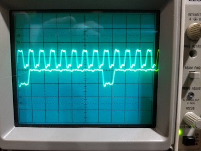
inverter.jpg [ 3.15 MiB | Viewed 270 times ]


And here's what the output looks like on "Fussy:"
Attachment:
inverter output.jpg
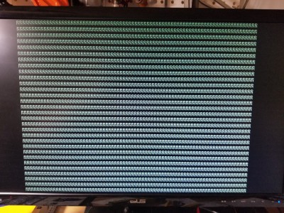
inverter output.jpg [ 6.02 MiB | Viewed 270 times ]


Here's with no inverter:
Attachment:
no inverter.jpg
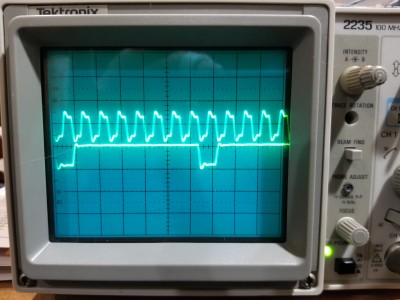
no inverter.jpg [ 3.23 MiB | Viewed 270 times ]


And the output with no inverter:
Attachment:
no inverter output.jpg
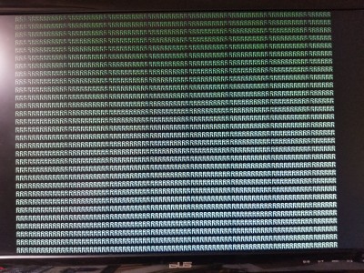
no inverter output.jpg [ 6.08 MiB | Viewed 270 times ]
Initially the output was also off by a pixel at the end of each line, but after an auto-adjust that cleared up. Still has those dark vertical bars though; I think you should be able to see them in the photo.

gfoot wrote:
Great to see. Where do VSYNC, VBLANK, and BLANK come from? More counters based on the shift register load signal, maybe going through logic gates to compare against key values? Is BLANK just for horizontal blanking or combined blanking?
They're generated by a timing ROM almost exactly like the one in your "Simplest Video Card." Since I'm not using it for image data, I had 5 spare bits to generate some other signals. I have had HBLANK\ and VBLANK\ since day one, and this week I added BLANK and BLANK\, which are combined blanking signals. I kept wanting them for various things and being forced to provide them with logic; I finally decided they were useful enough to add them to the ROM and ditch the extra ICs. :)

_________________
"The key is not to let the hardware sense any fear." - Radical Brad


Top
 Profile  
Reply with quote  
Display posts from previous:  Sort by  
Post new topic Reply to topic  [ 67 posts ]  Go to page Previous  1, 2, 3, 4, 5  Next

All times are UTC


Who is online

Users browsing this forum: No registered users and 9 guests


You cannot post new topics in this forum
You cannot reply to topics in this forum
You cannot edit your posts in this forum
You cannot delete your posts in this forum
You cannot post attachments in this forum

Search for:
Jump to: