6502.org Forum  Projects  Code  Documents  Tools  Forum
It is currently Sat Apr 27, 2024 2:03 am

All times are UTC


Post new topic Reply to topic  [ 558 posts ]  Go to page 1, 2, 3, 4, 5 ... 38  Next
Author Message
 Post subject: TTL 6502 Here I come
PostPosted: Tue Oct 20, 2015 2:04 am 
Offline
User avatar

Joined: Sun Oct 18, 2015 11:02 pm
Posts: 428
Location: Toronto, ON
Hello folks,

First post here and a big day for me.

I believe I now have a working model of a 6502 Logisim circuit that (I think) will translate well to a viable hardware implementation on 7400 series chips. It’s an important milestone on my way to building a TTL 6502 and (eventually) a C64 to host it. I was a complete newb to hardware design when this crazy project started (still am really), so this is a big deal to me. My first attempt was a totally impractical design (particularly the instruction decoder and sequencer which required well over a hundred nested gates and implemented only a heavily simplified version of the 6502 instruction set – see attached pic. It actually worked but what a monster!). I suppose it would have been advisable to start this foray into hardware design with a less ambitious project. Nevertheless, this is where I’ve landed and as you may be able to tell, I like jumping into things with both feet in any case.

There is no way for me to really know what will happen when I try to get this second (and much simpler) microcode-based design onto real chips, but I can at least be optimistic. I have tried to use only elements with ready 7400 series equivalents (no crazy 12 input gates, etc.), and tried also to meet their data sheet requirements as I went. Fingers crossed on how that will go. In the meantime, so far as I can tell, the Logisim simulation I have here is fairly accurate but with some differences worth noting. Here is a summary:

• Full 6502 instruction set, including all addressing modes, registers, decimal mode and RS, NMI, and IRQ interrupts,
• Microcode implementation (I wanted a minimum number of ROMs so kept some good ol’ gate-level decoding to stay within a 32 bit control word),
• Single 50% duty-cycle clock rather than the 6502 two-phase one (have to confess to not really understanding the requirement for two non-overlapping phases vs. using a single rising-edge to clock all flip-flops. The later seems much more straight forward. Any explanation on the trade-offs here would be very much appreciated),
• Official opcodes only (all illegal opcodes are NOPs, with the exception of $FA, $FC and $FF which are used for NMI, RS and IRQ microcode sequences respectively),
• Interrupts are recognized at the beginning of the instruction cycle but ignored once a given microcode sequence has begun (the simulation will not recognize an NMI, for example, once the microcode sequence for a lower priority IRQ is in progress),
• No SYNC line implemented (although I think I might be able to use the “Write to IR” control signal almost as is for this?)
• Address and Data busses are held in high-impedance state during phase 1 of the clock to facilitate a memory mapped screen RAM design,
• /BEN (Bus ENable) input pin tri-states the busses asynchronously when high (I think this is roughly equivalent to the 6510’s AEC pin. I might just drop this given the buses are already available during phase 1),
• The RESET sequence uses the 6502 “inhibited write” spare cycles to initialize the stack pointer and clear the decimal flag,
• ADC and SBC instructions take an extra cycle to complete in decimal mode, flags are updated but I still need to validate this is done properly, (Btw, I am amazed the 6502 can fit the binary operation and the BCD adjustment in one cycle! I found I had to split this into two cycles to get anywhere near reasonable propagation delay through all the required logic),
• JMP absolute instruction takes 4 cycles rather than 3 (this would have required some otherwise redundant logic to preserve the PC after fetching the low-byte of the target address. In the end, I decided the extra cycle was worth the savings in extra data path),
• A few other instructions take fewer cycles to complete than in a standard 6502 (e.g. LSR absolute-indexed instruction takes 6 cycles rather than 7 when a page boundary is not crossed - the microcode can easily be adjusted to add dummy cycles and retain more cycle compatibility in these instances. I will likely do that before finalizing the design just to minimize differences).

The design borrows heavily from Dieter Mueller’s multiplexer ALU as well as from multiple articles and posts found on this site about decimal mode, interrupt handling and many other aspects of the 6502’s behavior. I remember thinking that there might be scraps of information on the web about this obscure processor I had programmed as a kid. Instead, I was amazed to find a vibrant community of interest eager to share and learn. The fact that I've been able to get this far is largely due to this community. Many thanks to all of you for that.

On that note, I have run Klaus’ test harness (thank you Klaus) on this simulator and it appears to pass, although truthfully I’m not sure. I’ve read this test will run for about 1 minute at 2 MHz. It will take far longer than I am prepared to wait at the dismal 100Hz Logisim achieves. Nevertheless, I have run through all tests to completion, except the binary and decimal arithmetic tests. For those, I have run through a handful of iterations only (I gave up after three days) and have been forced to rely on unit tests for the time being. A more complete test will have to wait until I have a faster implementation.

I am happy to eventually post the Logisim files if this turns out to be of interest to anyone (and provided I get permission from those I have liberally borrowed from). Of course all comments and questions are welcome. I am particularly interested in ways to validate and simplify the design before going to hardware. I’ll post up some specific questions when I get a chance. As I mentioned, I’m new to hardware so can use all the help I can get.

My best to everyone here,

Drass

P.S. moderator: I posted this on the Hardware section because that's where I am headed. Please feel free to move it to the Simulation section if appropriate.


Attachments:
Control Logic.png
Control Logic.png [ 320.77 KiB | Viewed 20393 times ]

_________________
C74-6502 Website: https://c74project.com
Top
 Profile  
Reply with quote  
 Post subject: Re: TTL 6502 Here I come
PostPosted: Tue Oct 20, 2015 3:34 am 
Offline
User avatar

Joined: Fri Aug 30, 2002 1:09 am
Posts: 8428
Location: Southern California
Welcome!

Drass wrote:
I believe I now have a working model of a 6502 Logisim circuit that (I think) will translate well to a viable hardware implementation on 7400 series chips. It’s an important milestone on my way to building a TTL 6502 and (eventually) a C64 to host it. I was a complete newb to hardware design when this crazy project started (still am really), so this is a big deal to me.

Be sure to see Ruud Baltissen's Build your own 6502 with TTL (Hmmm... I just realized he hasn't posted here in ages)

Quote:
  • Single 50% duty-cycle clock rather than the 6502 two-phase one (have to confess to not really understanding the requirement for two non-overlapping phases vs. using a single rising-edge to clock all flip-flops. The later seems much more straight forward. Any explanation on the trade-offs here would be very much appreciated),

You're probably thinking too much in terms of registers instead of transparent latches. Ed is one who could tell you a lot more, being in on the visual6502 project.

Quote:
  • Address and Data busses are held in high-impedance state during phase 1 of the clock to facilitate a memory mapped screen RAM design,

That needs to change. 65xx I/O ICs require the address to be valid and stable for an amount of time before phase 2 rises. Otherwise they won't work. Also on RAM, adresses and R/W\ also need to be valid and stable a certain setup time before phase 2 rises, to make sure you can't write to random addresses while these are getting worked out.

Quote:
  • /BEN (Bus ENable) input pin tri-states the busses asynchronously when high (I think this is roughly equivalent to the 6510’s AEC pin. I might just drop this given the buses are already available during phase 1),

BE is positive logic on the 65c02 being made today, ie, bring high to assert, which is to enable buses. It's pin 36 of the DIP.

Quote:
  • The RESET sequence uses the 6502 “inhibited write” spare cycles to initialize the stack pointer and clear the decimal flag,

Clearing D is an automatic part of the 65c02 RST, IRQ, and NMI sequences.

Quote:
  • A few other instructions take fewer cycles to complete than in a standard 6502 (e.g. LSR absolute-indexed instruction takes 6 cycles rather than 7 when a page boundary is not crossed - the microcode can easily be adjusted to add dummy cycles and retain more cycle compatibility in these instances. I will likely do that before finalizing the design just to minimize differences).

LSR abs,X takes 7 cycles on NMOS 6502, 6 on CMOS 65c02.

Quote:
I remember thinking that there might be scraps of information on the web about this obscure processor I had programmed as a kid. Instead, I was amazed to find a vibrant community of interest eager to share and learn. The fact that I've been able to get this far is largely due to this community. Many thanks to all of you for that.

LOL, yes, the 6502 may be the best-documented processor in history. It is being made today at a rate of over a hundred million units a year, mostly going into automotive applications, industrial, appliance, toy, consumer electronics, and even life-support-- just not PCs. It is the only processor approved for in-body-implantable electronics. The fastest 65c02's are running over 200MHz.

Quote:
P.S. moderator: I posted this on the Hardware section because that's where I am headed. Please feel free to move it to the Simulation section if appropriate.

Here is fine.

_________________
http://WilsonMinesCo.com/ lots of 6502 resources
The "second front page" is http://wilsonminesco.com/links.html .
What's an additional VIA among friends, anyhow?


Top
 Profile  
Reply with quote  
 Post subject: Re: TTL 6502 Here I come
PostPosted: Tue Oct 20, 2015 8:31 am 
Offline
User avatar

Joined: Thu Dec 11, 2008 1:28 pm
Posts: 10793
Location: England
Indeed, welcome to our vibrant community - what an epic first post!

Garth is right, the 6502 clocking is related to the heavy use of transparent latches, which are half the cost of flip flops and also offer speed advantages - at the cost of very difficult to analyse timing behaviour. (The modern advice is to avoid latches. But they are sometimes just what you need.)


Top
 Profile  
Reply with quote  
 Post subject: Re: TTL 6502 Here I come
PostPosted: Wed Oct 21, 2015 1:49 am 
Offline
User avatar

Joined: Sun Oct 18, 2015 11:02 pm
Posts: 428
Location: Toronto, ON
Thanks for the warm welcome.

I did have a look at Ruud's site and have referred back at few times. Very helpful.

I think I'm going to stay with flip flops and a simple clock as far as I can. I don't have a firm grasp of techniques to deal with timing issues so I do expect challenges. Certainly I can leave the busses active during phase 1 to deal with setup times. But I'm not sure how the bus sharing scheme would work in that case. I could have the video logic steal the busses in phase 1 (using something akin to the 6510 AEC signal) and then given them back in time to meet the setup requirements but that seems like tricky timing. Are there any docs that shed some light on the C64 bus sharing scheme? I haven't been able to find much on this beyond the simple statement that it was done.

On a related note, a general question about clocking flip flops: I ran into a problem with spurious writes to registers in my design and tracked it down to clocking flip flops with a Write Enable signal gated with the system clock (through a simple AND gate). Turns out two edges reached the flip flops during cycles where the Write Enable line was going from low to high (played havoc with incrementing the Program counter, for example). To solve the problem I latched all Write Enable signals from the control logic and let them through only at the end of phase 2, coincident with the clock edge. This works well enough but left me wondering ... I don't see latches on write enable signals in other designs so there must be a simpler way of doing this. What am I missing?

And thanks for the notes on the 65C02. I "left the business" before that chip so don't know much about it. Nice to know those cycle times match where I ended up. Seems like an argument to leave well enough alone.

_________________
C74-6502 Website: https://c74project.com


Top
 Profile  
Reply with quote  
 Post subject: Re: TTL 6502 Here I come
PostPosted: Wed Oct 21, 2015 2:19 am 
Offline
User avatar

Joined: Mon May 25, 2015 2:25 pm
Posts: 632
Location: Gillies, Ontario, Canada
That would be one HUGE breadboard... I like it!
Great project, cheers!

Brad


Top
 Profile  
Reply with quote  
 Post subject: Re: TTL 6502 Here I come
PostPosted: Wed Oct 21, 2015 2:32 am 
Offline
User avatar

Joined: Sun Oct 18, 2015 11:02 pm
Posts: 428
Location: Toronto, ON
Thanks Brad. Been following your build for a while. Inspiring for sure.

I'm looking forward to the chips and wires ...

_________________
C74-6502 Website: https://c74project.com


Top
 Profile  
Reply with quote  
 Post subject: Re: TTL 6502 Here I come
PostPosted: Wed Oct 21, 2015 8:37 am 
Offline
User avatar

Joined: Thu Dec 11, 2008 1:28 pm
Posts: 10793
Location: England
AIUI, it's only a few older peripherals which clock inputs on the rising edge of phi2 and therefore can't coexist on a shared bus. Best to look carefully at the datasheets. For CPUs without a bus enable it would be normal to use some octal tristate buffers or muxes to allow for a shared address bus.


Top
 Profile  
Reply with quote  
 Post subject: Re: TTL 6502 Here I come
PostPosted: Wed Oct 21, 2015 12:46 pm 
Offline
User avatar

Joined: Sun Oct 18, 2015 11:02 pm
Posts: 428
Location: Toronto, ON
Thanks BigEd. That helps.

Since it's discreet logic unit it doesn't much matter whether the bus enable is "in" the cpu or "out" so for the sake of completeness I'll leave the BE line in. Seems also like an asynchronous enable/disable is adequate and the video logic needs to handle with care. i'll go with it for now and come back to it later when actually trying to interface this with peripherals.

Btw BigEd, I can't imagine anyone not having to pick up their jaw off the ground after seeing the visual 6502 for the first time. Amazing!

Cheers

_________________
C74-6502 Website: https://c74project.com


Top
 Profile  
Reply with quote  
 Post subject: Re: TTL 6502 Here I come
PostPosted: Wed Oct 21, 2015 2:17 pm 
Offline

Joined: Wed Sep 23, 2015 8:14 pm
Posts: 171
Location: Philadelphia, PA
Drass wrote:
On a related note, a general question about clocking flip flops: I ran into a problem with spurious writes to registers in my design and tracked it down to clocking flip flops with a Write Enable signal gated with the system clock (through a simple AND gate). Turns out two edges reached the flip flops during cycles where the Write Enable line was going from low to high (played havoc with incrementing the Program counter, for example). To solve the problem I latched all Write Enable signals from the control logic and let them through only at the end of phase 2, coincident with the clock edge. This works well enough but left me wondering ... I don't see latches on write enable signals in other designs so there must be a simpler way of doing this. What am I missing?

On FPGAs, using gated clocks is considered bad design practice. I think it has to do with the fact that the gated output will likely not be able to use the dedicated clock routing resources. But since your design is discrete logic, I can think of no reason not to use gated clocks except this: it makes timing analysis very difficult. Unless you have a way to accurately simulate your design to find these sorts or problems, or fancy spending many hours with your circuit and a good logic analyzer, your idea of latching the write enable signals seems a reasonable compromise.


Top
 Profile  
Reply with quote  
 Post subject: Re: TTL 6502 Here I come
PostPosted: Wed Oct 21, 2015 2:47 pm 
Offline
User avatar

Joined: Tue Nov 16, 2010 8:00 am
Posts: 2353
Location: Gouda, The Netherlands
Gated clocks also introduce the risk of glitches, which can be interpreted as additional clock cycles.


Top
 Profile  
Reply with quote  
 Post subject: Re: TTL 6502 Here I come
PostPosted: Wed Oct 21, 2015 2:54 pm 
Offline
User avatar

Joined: Thu Dec 11, 2008 1:28 pm
Posts: 10793
Location: England
(
Drass wrote:
Btw BigEd, I can't imagine anyone not having to pick up their jaw off the ground after seeing the visual 6502 for the first time. Amazing!

Agreed! I jumped in after the extraction and simulation but just before the website came up. Since when I've helped with the website and with investigations. This was the moment of discovery:
viewtopic.php?p=11590#p11590
And concurrently at
viewtopic.php?p=11582#p11582
)


Top
 Profile  
Reply with quote  
 Post subject: Re: TTL 6502 Here I come
PostPosted: Fri Oct 23, 2015 3:21 am 
Offline
User avatar

Joined: Sun Oct 18, 2015 11:02 pm
Posts: 428
Location: Toronto, ON
I thought I would start to describe various aspects of the design and then ask questions as they come up. I’m thinking this combined approach might be valuable to other hardware newbs like myself. My journey here started nearly at ground zero so it’s baby steps all the way. For folks that know what they are doing: please bare with us and feel free to comment on the good and the ugly. I fully expect that there will be significant shortcomings to address as we go.

Now, given the objective is to learn, I set myself some design guidlines at the start:

1) Don’t use a chip unless I understand what is going on inside – which pretty much restricts me to simple ICs (muxes, decoders, latches, etc.). Keep away from higher-density ICs like 74181 sor 74182s,

2) Do as much as possible in discrete logic even at the cost of slower performance (i.e. no lookup ROMs for the ALU, keep control ROMs to a minimum),

3) The result needs to be a fully functional processor accurate enough to be genuingly called a 6502. The practical “acid test” is to be able to run a game I wrote for the C64 back in 1983 (amazingly, I was able to download a copy from the web 30 years after I had written it! I even found an original, unopened shrink-wrap copy in an eBay store – cassette and all. Wow).

Before we get going, I’ll just mention a couple of resources I found useful as a complete neophyte (I certainly needed “paint by numbers” at the start). For digital logic basics, try http://www.robotbrigade.com/digitalLogic.php. For CPU design basics, Donn Stewart’s http://www.cpuville.com is great.

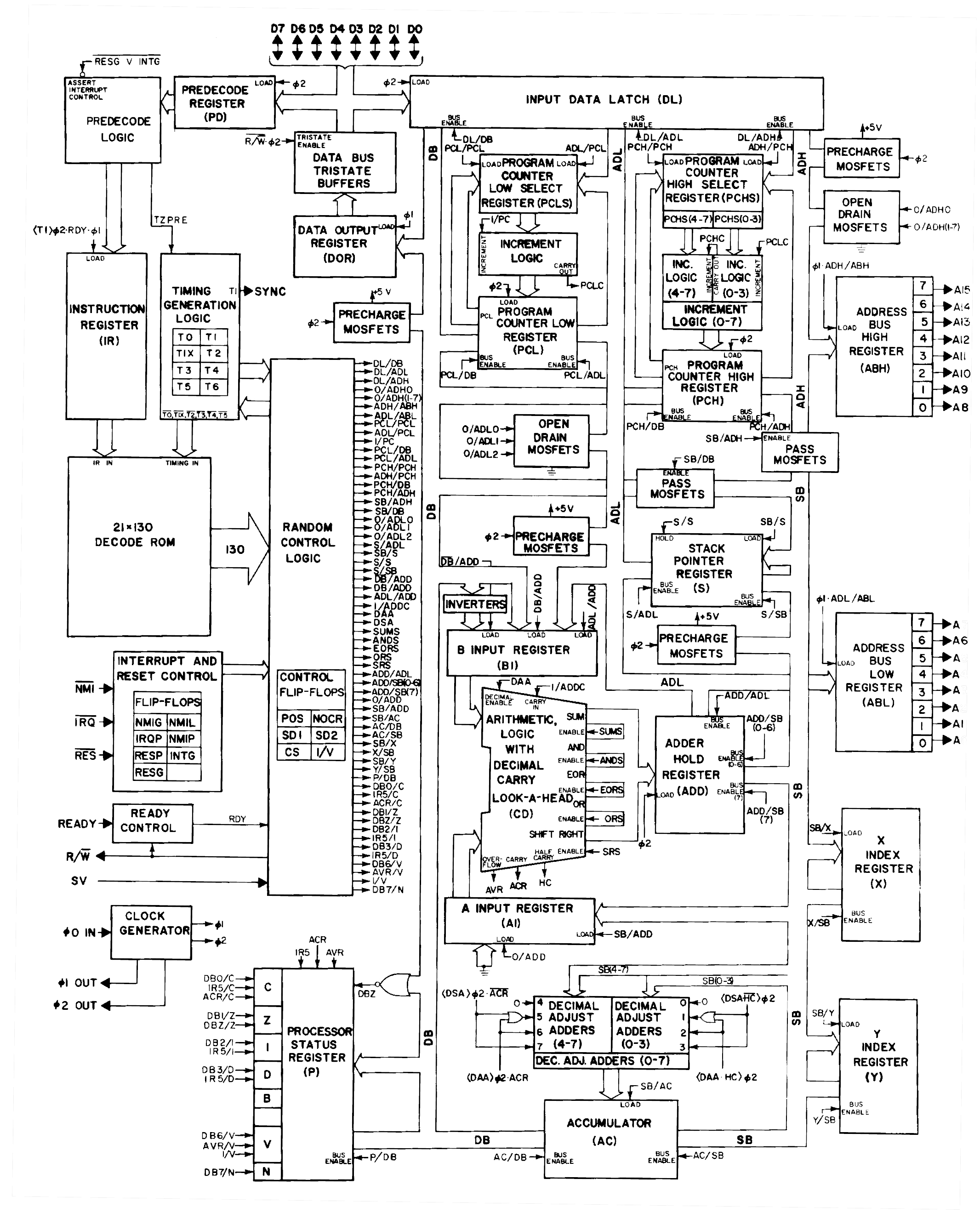
Ok, first up, a block diagram:
Attachment:
6502 Block Diagram.png
6502 Block Diagram.png [ 104.69 KiB | Viewed 20190 times ]

Busses are on the sides, 8-bit wide registers in the middle. The W Bus on the left is used to write to registers and the R bus on the right to read from them. Outputs from registers to the “R” bus are tri-state (74HC574s with Output Enable signals). For a memory write, data flows from a register to the R Bus and from there to the external Data Bus on its way to memory. Similarly, reads go from memory through the Data Bus and W Bus to a destination register. Transfers between registers travel through the ALU to get from R Bus to W Bus. The ALU takes its second operand from memory through the B register (the B register is required only to spread the long journey from memory through ALU over two cycles).

For addressing, PCL/PCH together make up the program counter. Similarly, DPL/DPH make up the “Data Pointer” which is used to resolve target addresses. Both PC and DP can be output to the internal Address High (ADH) and Address Low (ADL) busses, and from there to the external Address Bus. The stack pointer SP can be output to ADL and is paired with an “$01” in ADH for Page 1 Stack Addressing. The ADH can also generate “$00” for Zero-page addressing and “$FF” to fetch interrupt vectors high in memory. Similarly, the box labelled “$FA, $FC, $FE, $FF” refers to contants that can be placed on the R Bus and loaded into DPL as the low-byte of interrupt vector addresses. The “$FF” constant is also used to initialize the SP register on Reset. Finally, the T register can be used directly as the low-byte of a target address, which saves a cycle during Indirect Addressing operations.

The INC16 circuit is capable of 16-bit increment/decrement operations in parallel with the ALU. It takes its input from ADL/ADH and is used to increment PC, as wel as to manipulate SP for stack push and pull operations. Another parallel data path allows the DPH and I registers to be loaded directly from memory (in addition to the normal path throught the W Bus). Both these “parallel” capabilities were necessary only to try to match 6502 cycle counts on specific instructions.

To illustrate how I'm using this machinery, below is the microcode for an LDA absolute instruction:
(“*” denotes dereferincing an address, “+=” denotes an INC16 operation, “:=” denotes a data transfer)

I := *PC; PC += 1 : Fetch Opcode : Output enable the PC onto the address bus. Load IR from the W Bus. Load PC from the INC16 S Bus.
DPl := *PC; PC += 1 : Fetch ADL : Output enable the PC onto the address bus. Load DPL from the W Bus. Load PC from the INC16 S Bus.
DPh := *PC; PC += 1 : Fetch ADH : Output enable the PC onto the address bus. Load DPH from the W Bus. Load PC from the INC16 S Bus.
A := *DP; SETF(NZ); END : Load A : Output enable DP on to the address bus. Load A from the W Bus. Set N and Z flags. End the sequence.

Now for some questions:
• 6502 block diagrams depict bi-directional connections from registers to various internal busses. Although I get the advantages of a bi-directional bus, having two independant buses allows me to read from and write to a given register in the same cycle (i.e., when incrementing a register, for example). Does the 6502 have bi-directional buses internally or is it just a short-hand? If bi-directional, how are register increments accomplished in one cycle?
• I often see a Memory Address Register (MAR) connnected directly to the address bus in various CPU designs. I have to confess I don’t really understand why they are needed. So far as I can tell, the extra cycle(s) required to move an address to the MAR can be avoided by using tri-state buffers on the outputs of various registers and using them directly. I have to believe I am missing something here. Why move the contents of the PC to a MAR when one can output-enable the PC register directly onto the address bus?
• I could think of no way to generate constants on the R Bus other than by wiring specific values behind a dedicated tri-state buffer (74HC541). Seems like a heavy handed approach. How do folks normally accomplish this?
• I understand that it can be fatal to have IC outputs connected together while not in a high impedance state. Control logic can regulate this on a bus but how does one avoid the inevitable collisions at the point of transition – when one register is “coming up” while another is “going down”?
• Does anything here look like it's going to land me in hot water come implementation?

Ok, that's it for now. Thanks in advance for your comments and thoughts.

Best,

Drass.

_________________
C74-6502 Website: https://c74project.com


Top
 Profile  
Reply with quote  
 Post subject: Re: TTL 6502 Here I come
PostPosted: Fri Oct 23, 2015 4:52 pm 
Offline
User avatar

Joined: Thu Dec 11, 2008 1:28 pm
Posts: 10793
Location: England
Here's a quick demo using visual6502:
http://visual6502.org/JSSim/expert.html ... loglevel=1
If you look hard enough, and perhaps cross-reference with Hanson's big block diagram, you'll see for example that X is at different times read from and written to over the Special Bus (XSB and SBX control this) - and indeed, the SB is the only way to access X (and Y too). Anything other than the PC which is incremented or modified will be fed to the ALU in one cycle and then written back in the following cycle or later - there's no same-cycle operation.

Having said which, in fact S can be read and written in one cycle, but with unrelated values. See the use of S to store the first operand byte of JSR while the previous content is sent to the ALU to be decremented, about cycle 19 of the demo.

Of course, as your microarchitecture is different, you'll have different capabilities and different constraints. Thanks for the block diagram - I find that the easiest way to get a grip on things like this.

If you use wire-OR or wire-AND for your busses - or even an explicit OR or AND construction - you can get some constants for free. I think the 6502 gets FF for free by using a precharged bus. Constants like FC then only cost a couple of pull-downs.

I suspect momentary driver conflicts are not much of an issue - if there were an issue, you might need some complicated clocking using multiple non-overlapping phases. I think the case to worry about is corruption of a value being written (or corruption of a write-enable.) Certainly you don't want to have driver conflicts for a full phase or full cycle.

It might be that the MAR is actually a latch - it doesn't cost a cycle, but it holds the value it's been given and so allows the bus which feeds it to be reused. The 6502 has some slightly odd latching in the path from the databus to the address bus. (When the high byte of an absolute address appears late in one cycle on the databus, it needs to appear early in the next cycle on the address bus.)

BTW, can I suggest you tweak a couple of your names?
- use IR instead of I
- use DPH and DPL instead of DPh and DPl
- likewise for PCH and PCL
I think it'll help legibility.


Top
 Profile  
Reply with quote  
 Post subject: Re: TTL 6502 Here I come
PostPosted: Fri Oct 23, 2015 9:28 pm 
Offline
User avatar

Joined: Sun Oct 18, 2015 11:02 pm
Posts: 428
Location: Toronto, ON
Thank you very much for this Ed. The Visual 6502 trace is a real eye opener. I can clearly see XSB and SBX on alternate cycles. It's fascinating how different this is from where I ended up. For INX, for example, I do the round trip through ALU in one cycle, which ties up all the busses and probably incurs greater propagation delay through all the circuitry (it may, hoverer, also simplify the microcode logic). I'm going to study this trace in more detail to really get what's going on.

Yes, my total lack of EE background probably accounts for not wanting to venture into wired-logic options. I should probably just get a few open collector gates and experiment. Anyway, I decided to try to use standard gate logic and wire up the constants based on control line values and use a single bus buffer (74HC541) to control access to target bus. Below is what I came up with for the R Bus values (R.MX2 and R.MX3 are both high when the circuit is used. /FF.R, /FE.R, /FC.R and /FA.R are control lines to select the given values to be placed on the R Bus).
Attachment:
CONST.png
CONST.png [ 7.74 KiB | Viewed 20122 times ]

I don't have any cycle or phase-long conflicts on the busses according to Logisim, . I'm clocking all the bus-enable control lines at the start phase 1 at the same time. Only one remains asserted for the remainder of the cycle after the initial transition. The concern is really only the brief moment when the clock edge hits and control lines turn on and off. The propagation delay through the control logic is pretty consistent for the various output-enable control lines (maybe differing only by a gate or two) so I expect the potential overlap is probably less than 20 nanoseconds using HC logic. So if that's ok, the current arrangement should work as is. The write-enable values should be ok since they are only used in phase 2, long after everything should have settled.

I may need to get a better grip on transparent latches after all. Seems like I'm missing some subtleties that may prove important here. I'm currently using strictly edge-triggered D-type and I have more propagation delay from the address registers to the address bus than I'd like. Perhaps using a different latching strategy may be the solution. Likely a challenge for another day though as the first priority is for the thing to work, even if the clock frequency is lower than otherwise.

I like your legibility suggestions. Adopted.

Thanks again for your comments. It's very helpful and I'm gaining some confidence that the design might be viable on the whole. I think I'm going to finish up a schematic of the registers and share that to get further feedback.

Cheers.

_________________
C74-6502 Website: https://c74project.com


Top
 Profile  
Reply with quote  
 Post subject: Re: TTL 6502 Here I come
PostPosted: Fri Oct 23, 2015 10:07 pm 
Offline
User avatar

Joined: Sun Oct 18, 2015 11:02 pm
Posts: 428
Location: Toronto, ON
Arlet wrote:
Gated clocks also introduce the risk of glitches, which can be interpreted as additional clock cycles.


I just wanted to come back to this point again and ask what sorts of glitches you are referring to. Do you mean stray electrical pulses or timing issues as logic changes? I certainly was seeing additional clock cycles on the WR lines and I think these had to do with how the signals travelled through the control logic. Since it's all in a simulator, though, I'm wondering if there are other electrical things happening that I don't have any awareness of.

For the time being, I'm taking jmp(FFFA)'s suggestion of keeping the write signals latched.

Thanks for your comments guys.

_________________
C74-6502 Website: https://c74project.com


Top
 Profile  
Reply with quote  
Display posts from previous:  Sort by  
Post new topic Reply to topic  [ 558 posts ]  Go to page 1, 2, 3, 4, 5 ... 38  Next

All times are UTC


Who is online

Users browsing this forum: No registered users and 22 guests


You cannot post new topics in this forum
You cannot reply to topics in this forum
You cannot edit your posts in this forum
You cannot delete your posts in this forum
You cannot post attachments in this forum

Search for:
Jump to: