6502.org Forum  Projects  Code  Documents  Tools  Forum
It is currently Fri May 03, 2024 5:28 am

All times are UTC


Post new topic Reply to topic  [ 26 posts ]  Go to page 1, 2  Next
Author Message
 Post subject: My 65c816 SBC project...
PostPosted: Mon Aug 12, 2019 8:45 pm 
Offline
User avatar

Joined: Wed Feb 14, 2018 2:33 pm
Posts: 1401
Location: Scotland
So last year (2018), in my 40th anniversary of being a 6502 programmer, I made myself a little 6502 (actually 65C02) SBC. Links here http://forum.6502.org/viewtopic.php?f=4&t=5657&p=69744#p69744 and here https://projects.drogon.net/6502-ruby/

This is working very well, but I really wanted to dabble with the 65816, however round about that time Dave Murray (The 8-bit guy) was talking about his dream 8-bit computer and it looked like he might go with the 65816 so I felt I'd stick with the 6502 and let someone else build the 65816 system... At least one person jumped to the task and created the Foenix C256 which looked promising, but I was put off that project by a few things, then the Neon816 project was kicked off and that looks promising, meanwhile Daves project has turned into a somewhat mediocre (for me when I compare it to my favourite 80's 6502 system the BBC Micro) 65C02 system, so that's off the cards from the 65816 point of view.

Meanwhile, I'd build up my 65C02 system write loads of software for it, gotten BASICs to run, graphics, "the usual" - there is a little video demo of it here:

https://www.youtube.com/watch?v=ci_70naIg_Q another here is a C program drawing circles: https://www.youtube.com/watch?v=rPGCT0lah4Q

then I upgraded it to a 65816 system, https://projects.drogon.net/ruby-6502-becomes-ruby-65816/ but decided to press ahead with my own '816 system.

And here it is - or at least a working prototype:

Attachment:
IMG_20190812_210957_DRO.jpg
IMG_20190812_210957_DRO.jpg [ 472.09 KiB | Viewed 2209 times ]


It shares the bootstrap, serial and filesystem IO system that my 6502 system has - namely an ATmega 1284p.

There are 2 GALs - one doing the same as my earlier 65C02 system to replace some glue to do address decoding and memory r/w qualifying and the other to latch the top 8 address bits from the data bus (and some extra glue to OR the IRQs together) The 65816 is running at 16Mhz as was my 65C02 system. This currently has 512KB of RAM, but it's expandable to 1MB by using the same double-stacking trick I did on the 6502 board, however when I looked at the applications I was after running, I felt that 512KB was more than enough for a retro style system and I could put 2 sockets in and might still, but I was happy with the stacking trick I did before.

(And retro was still name of the game here - so through hole components, ULAs were common in micros c1981, PAL and GALs in the early to mid 80's - however using an ATmega and SD card - well, not so retro, but I really didn't want a floppy disk!)

So now it's back to the OS - upgrading bits of it to run in 816 mode while maintaining compatibility with the Acorn MOS style interface it currently has, but putting the '816 into my 65C02 system has given me some good experience there - I can still run all the 8-bit BASICs (BBC Basic, Applesoft, EhBASIC, CBM Basic v2, etc.) but in emulation mode. I'm also running some C code on it, but cc65 only generates 6502 code for now, however I'm looking at some other compilers (not C) that will run directly on the hardware without the need for cross compiling (mostly because that's all we had in the 80's - cross assemblers did exist in the 70's but in the 80's? My experience is that it was all done natively)

And while this is an SBC - ie. Single Board Computer, I have plans for an add-on interface connected via the 6522 which will stop it being a single board, but that's really to give me more GPIO and faster graphics than the 115200 baud serial line allows.

Cheers,

-Gordon

Ps. For anyone else building a 6502 retro system - unless you're really going for the old NMOS experience, then do go with the 65816 on day 1 - even if you just run it in emulation mode with 64KB of RAM, you'll have the option of all those '816 instructions if you need them - I now wish I had, however knowing that it's just a one resistor change to go from 65C02 to 65C816 wasn't that bad, really.

_________________
--
Gordon Henderson.
See my Ruby 6502 and 65816 SBC projects here: https://projects.drogon.net/ruby/


Top
 Profile  
Reply with quote  
PostPosted: Mon Aug 12, 2019 9:05 pm 
Offline
User avatar

Joined: Tue Mar 05, 2013 4:31 am
Posts: 1373
Very nice indeed!

You're getting more projects done than I am lately... but I am looking at implementing an updated floppy setup to my 'C02 Pocket SBC. Any schematics or details available for your latest Ruby?

_________________
Regards, KM
https://github.com/floobydust


Top
 Profile  
Reply with quote  
PostPosted: Mon Aug 12, 2019 9:07 pm 
Offline
User avatar

Joined: Thu Dec 11, 2008 1:28 pm
Posts: 10793
Location: England
Wow - that circles demo is impressive! (Is that because the pixel-pushing work is somewhat offloaded to the host, in this case the terminal emulator?)

But anyway, a nice board, and a promising platform.

I do like the prospect of native development. In the world of Z80 and CP/M it wasn't at all uncommon to have native compilers, I think.


Top
 Profile  
Reply with quote  
PostPosted: Mon Aug 12, 2019 9:25 pm 
Offline
User avatar

Joined: Wed Feb 14, 2018 2:33 pm
Posts: 1401
Location: Scotland
floobydust wrote:
Very nice indeed!

You're getting more projects done than I am lately... but I am looking at implementing an updated floppy setup to my 'C02 Pocket SBC. Any schematics or details available for your latest Ruby?


Not sure a schematic would help - it really is join the dots from the 65816 via 2 GALS into the RAM and 65C22. One GAL has the 8 data bus lines going into it and ph2 and BE, the other has ph2, BE, AD [8:15] going in to decode the /Rd and /Wr and /Ce for the RAM and the /Ce 65c22 - there is signal from the first GAL to the 2nd to indicate bank 0, so the IO doesn't decode on all Banks... if I knew abut CPLDs then I could do all that inside one CPLD (especially knowing it's been done before). Also if I was more confident in my PCB layout "Fu" then I'd stick a 2nd SRAM socket.

The rest is the ATmega - it puts out AD[0:7] into the SRAM and D[0:7] also into the SRAM, and reads the Rdy signal, controls Reset and BE to the 65816.

Or maybe I'm making it sound too simple, or just embarrassed that I'm (still) using Fritzing :-)

-Gordon

_________________
--
Gordon Henderson.
See my Ruby 6502 and 65816 SBC projects here: https://projects.drogon.net/ruby/


Top
 Profile  
Reply with quote  
PostPosted: Mon Aug 12, 2019 9:33 pm 
Offline
User avatar

Joined: Wed Feb 14, 2018 2:33 pm
Posts: 1401
Location: Scotland
BigEd wrote:
Wow - that circles demo is impressive! (Is that because the pixel-pushing work is somewhat offloaded to the host, in this case the terminal emulator?)

But anyway, a nice board, and a promising platform.

I do like the prospect of native development. In the world of Z80 and CP/M it wasn't at all uncommon to have native compilers, I think.


It certainly wasn't. I used FORTRAN, C and Pascal under CP/M and while not perfect, it did seem more self-contained than ther 6502 systems at the time. I did use Aztec C on the Apple II though - it was very slow, but got there in the end, but on the Apple II (and others), there was the UCSD P system, and while I'm not that enamoured by Pascal, it's something I'll be looking at along with some other ideas.

And yes, the circles - they are drawn by the graphics terminal emulator, so the 6502 host just sends control codes to the terminal and it does the hard work. This is similar to the Tektronix 4014 serial terminals of the 70's and 80's (and still today in xterm -t, but no-ones uses it anymore) and identical to the way the BBC Micro did in the 1981. (See the end of the first video where I draw a triangle from BBC Basic)

Cheers,

-Gordon

_________________
--
Gordon Henderson.
See my Ruby 6502 and 65816 SBC projects here: https://projects.drogon.net/ruby/


Top
 Profile  
Reply with quote  
PostPosted: Tue Aug 13, 2019 1:16 pm 
Offline
User avatar

Joined: Fri Dec 12, 2008 10:40 pm
Posts: 1000
Location: Canada
Nice!

What terminal emulator software are you using?

_________________
Bill


Top
 Profile  
Reply with quote  
PostPosted: Tue Aug 13, 2019 2:27 pm 
Offline
User avatar

Joined: Wed Feb 14, 2018 2:33 pm
Posts: 1401
Location: Scotland
BillO wrote:
Nice!

What terminal emulator software are you using?


The RubyOS will use a standard "ANSI" type terminal, so I use minicom under Linux for text based stuff, but the graphical one is something I wrote in C that uses the SDL library. It's actually the front-end screen/keyboard IO system that is part of a Linux based BASIC interpreter I wrote a few years back - I just put in a bit of code to read/write a serial port and interpret the codes to do things like move cursor, plot character, line, circle, etc.

The Acorn (BBC Micro) OS defined a whole slew of codes back in the early 80's for BBC Micro software, so it was easy to just pick that up use use it, so I could run BBC Basic programs relatively easy - the BBC Micro de-coupled the BASIC (or any other language) from the OS, so applications all had a common interface be they BASIC, Forth, Comal, C, Pascal and so on. As long as they stuck to the (Acorn) standards then they could do stuff on the screen (pixel poking was sort of frowned on - mostly because your program could be running on an external 2nd processor with no direct access to the physical screen memory) The startup code in the ATmega detects "dumb" ansi or smart graphics terminal, and can re-work the standard OS codes into ANSI codes, so screen editors work on a text terminal and graphics codes get passed through when it knows it's a graphical one.

So a BASIC program outputs chr$(12) to clear the screen, and if it's an ANSI terminal, then the ATmega translates this into the correct ANSI clear screen code (ESC [2J) or passes it through to the graphical terminal unchanged for it to deal with.

So the usual ones we know - CR (13), LF (10) and BELL (6), plus some other well-known ones - 12 to clear the screen and so on. "Plot" is a generic if complex one that takes a single byte for a code then a pair of 16-bit numbers for X and Y, so 6 bytes in total. Re-define a character/font entry is similar based on an 8x8 bit font, so 8 bytes plus the character code to reprogram. I can define and move sprites and tiles the same way too and do sound (when I get round to it), although that 115200 baud link start to be limiting, so moving to an 8-bit parallel interface will be much faster to a dedicated little microcontroller will speed that up somewhat.

BBC Basic has a few built-in keywords to do some of these - e.g. CLS, GCOL, COLOUR, PLOT and so on, also a handy chr$() function called vdu, so

Code:
vdu 12


is the same as

Code:
print chr$(12);


and so on.

Hm. Maybe I ought to look into Tex 4014 mode again ...

Cheers,

-Gordon

_________________
--
Gordon Henderson.
See my Ruby 6502 and 65816 SBC projects here: https://projects.drogon.net/ruby/


Top
 Profile  
Reply with quote  
PostPosted: Mon Nov 25, 2019 4:55 am 
Offline

Joined: Mon Nov 25, 2019 4:46 am
Posts: 19
can someone please point me towards a simple example of how a 65c816 implements the high order A16 thru A23 address bits? I've read in the datasheet how the processor can address 16 MegaBytes of RAM, but I have yet to see a circuit example showing how this can be done.


Top
 Profile  
Reply with quote  
PostPosted: Mon Nov 25, 2019 5:06 am 
Offline
User avatar

Joined: Fri Dec 11, 2009 3:50 pm
Posts: 3350
Location: Ontario, Canada
Welcome, N2- :)

You'll need a latch (such as 74xx373 or '573) to capture the Bank Address bits (aka A16 thru A23). See Figure 5-1 in the WDC datasheet.

-- Jeff
Attachment:
Fig 5-1.png
Fig 5-1.png [ 10.19 KiB | Viewed 1974 times ]

_________________
In 1988 my 65C02 got six new registers and 44 new full-speed instructions!
https://laughtonelectronics.com/Arcana/ ... mmary.html


Top
 Profile  
Reply with quote  
PostPosted: Mon Nov 25, 2019 5:14 am 
Offline
User avatar

Joined: Fri Aug 30, 2002 9:02 pm
Posts: 1683
Location: Sacramento, CA
Well, Jeff beat me to it....


Page 44 of the current 65816 datasheet on the WDC web page has a circuit.

https://www.westerndesigncenter.com/wdc ... 5c816s.pdf

Its basically a transparent latch (74xx373 or 74xx573) clocked by an inverted PHI2.

Daryl

_________________
Please visit my website -> https://sbc.rictor.org/


Top
 Profile  
Reply with quote  
PostPosted: Mon Nov 25, 2019 8:48 am 
Offline
User avatar

Joined: Wed Feb 14, 2018 2:33 pm
Posts: 1401
Location: Scotland
FWIW: I didn't use the reference circuit in my '816 system. I used a single GAL. This doesn't work in transparent latch mode which the reference circuit seems to require (although I don't know why the reference circuit needs this)

The GAL takes the 8 address line inputs and feeds them directly to 8 outputs set to 'register' mode and uses ph2 as the latch (register) trigger, latching them on every rising edge of ph2. These outputs are held during ph2 high and the subsequent low half cycle, being re-sampled/latched on the next ph2 high transition. (Actually, while I take all 8 data lines input I only output A[16:20] as that's all I'm using - although I'm really only using A[16:18] as I have a 512KB memory chip, but there's space to vertically mount a 2nd if I think I need it. (the same GAL does some other stuff too - like 'wire-or the IRQs to the '816)

The rest of the design takes A[8:15] into another GAL which is the address decoder... There is no separate data bus transceiver,and again, I'm not sure why it's needed in the reference circuit. I'm sure I'm out of spec. somewhere along the line, but it works very reliably at 16Mhz, so I'm happy.

-Gordon

_________________
--
Gordon Henderson.
See my Ruby 6502 and 65816 SBC projects here: https://projects.drogon.net/ruby/


Top
 Profile  
Reply with quote  
PostPosted: Mon Nov 25, 2019 1:03 pm 
Offline
User avatar

Joined: Fri Dec 11, 2009 3:50 pm
Posts: 3350
Location: Ontario, Canada
drogon wrote:
There is no separate data bus transceiver,and again, I'm not sure why it's needed in the reference circuit.
The transceiver can be omitted, but doing so makes it harder, timing-wise, for other devices to share the data bus cleanly. Specifically, there's a prominent risk of bus contention transients which last for a fraction of a cycle. Either the other devices (memory and IO) need to be precisely timed, or the contention transients must simply be tolerated. The latter approach increases power consumption, and supply noise. This can be enough to bring down the system, as in this remarkable case.

In contrast to the '816's data bus, the 6502's spends 50% of its time in tri-state (floating). Contention is impossible during this time, and thus there's a generous timing cushion for devices to start and stop driving the bus. Adding a transceiver to an '816 design provides the same "timing cushion" effect for memory and IO devices attached to the bus. See Managing the 65816 multiplexed bus.

-- Jeff

Image

_________________
In 1988 my 65C02 got six new registers and 44 new full-speed instructions!
https://laughtonelectronics.com/Arcana/ ... mmary.html


Last edited by Dr Jefyll on Mon Nov 25, 2019 1:24 pm, edited 1 time in total.

Top
 Profile  
Reply with quote  
PostPosted: Mon Nov 25, 2019 1:21 pm 
Offline
User avatar

Joined: Wed Feb 14, 2018 2:33 pm
Posts: 1401
Location: Scotland
Dr Jefyll wrote:
drogon wrote:
There is no separate data bus transceiver,and again, I'm not sure why it's needed in the reference circuit.
The transceiver can be omitted, but doing so makes it harder, timing-wise, for other devices to share the data bus cleanly. Specifically, there's a prominent risk of bus contention transients, lasting for only a fraction of a cycle. Either the other devices need to be precisely timed, or, you're obliged to tolerate the contention transients.

In contrast to the '816's data bus, the 6502's spends 50% of its time in tri-state (floating). Contention is impossible during this time, and thus there's a generous timing cushion for devices to start and stop driving the bus. Adding a transceiver to an '816 design provided the same effect. See Managing the 65816 multiplexed bus.


Well, indeed. I have read every bit of '816 bus timing I could get my hands on. Watched animated GIFs with interest, counted nanoseconds and dug into other peoples designs too.

But I have a board that works at 16Mhz. (See the post that started this thread for a picture of it) I have one peripheral - a 65C22 and one memory chip (512KB SRAM) The memory also has shared access to an ATmega, but that's not at bus speed. I don't have the tools to tell me it should not be working, but it runs all the code I throw at it, memtests, moves, arithmetic tests and so on. It's been running 24/7 for the past few months. I'm happy. It's not perfect but it's simple and does everything I want out of an '816 system. I think that sometimes you just have to suck it and see.

-Gordon

_________________
--
Gordon Henderson.
See my Ruby 6502 and 65816 SBC projects here: https://projects.drogon.net/ruby/


Top
 Profile  
Reply with quote  
PostPosted: Mon Nov 25, 2019 1:30 pm 
Offline
User avatar

Joined: Fri Dec 11, 2009 3:50 pm
Posts: 3350
Location: Ontario, Canada
drogon wrote:
It's not perfect but it's simple and does everything I want out of an '816 system. I think that sometimes you just have to suck it and see.
Yes, certainly -- I don't contest that. :) Do I seem to be coming on too strongly? My very first words were, "The transceiver can be omitted."

But there's an attendant compromise. IMO, builders who are less experienced than you would be well advised to include the transceiver, and even seasoned veterans should think twice before dispensing with it.

-- Jeff

_________________
In 1988 my 65C02 got six new registers and 44 new full-speed instructions!
https://laughtonelectronics.com/Arcana/ ... mmary.html


Top
 Profile  
Reply with quote  
PostPosted: Mon Nov 25, 2019 11:36 pm 
Offline
User avatar

Joined: Thu May 28, 2009 9:46 pm
Posts: 8172
Location: Midwestern USA
Dr Jefyll wrote:
Do I seem to be coming on too strongly? My very first words were, "The transceiver can be omitted."

But there's an attendant compromise. IMO, builders who are less experienced than you would be well advised to include the transceiver, and even seasoned veterans should think twice before dispensing with it.

My POC V1 design was built without the bus transceiver and was stable at 15 Mhz without the SCSI host adapter being plugged in. I never dug into the timing far enough to determine if it was due to sheer, dumb luck or due to the conservative nature of the '816's design.

There's no question that a risk of bus contention exists at the transition from Ø2 low to Ø2 high. The '816 timing diagram implies that the bank bits persist beyond the transition, apparently by tBH, which is 10ns on 5 volts, if one can believe the AC characteristics data chart. This means, of course, the data bus is still being driven by the '816 after the rise of Ø2, apparently for 10ns (worst case). Assuming a read operation is gated by Ø2 high, the lag between Ø2 high and the presence of device output on D0-D7 will be determined by the gate prop time needed after the low-to-high transition of Ø2 to generate the "read data" signal (e.g., /RD) at the addressed device plus the time required for the device to respond to negation of /OE and start driving the bus. If that cumulative time is equal to or less than tBH some contention will occur.

In revisiting my POC V1.1 design, my read/write circuitry's total prop time from the rise of Ø2 to when /RD goes low is a single gate delay caused by the 74AC00 NAND that drives /RD (see below).

Attachment:
File comment: POC V1.1 Read/Write Generation
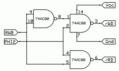
read_write_qualify_alt.gif
read_write_qualify_alt.gif [ 46.98 KiB | Viewed 1892 times ]

Best-case prop time on the 'AC00 at 5 volts is 1.9ns (worst case is 6.6ns), which means /RD would go low before the expiration of tBH (even at worst-case performance, /RD would be low before the expiration of tBH). The fastest device in the system is the SRAM, which can switch from hi-Z to active mode in 6ns or less when its /OE is negated. Doing the math suggests the SRAM could start driving the bus before the expiration of tBH—bear in mind that as soon as the SRAM comes out of hi-Z it is a bus driver. This would come about if the NAND and the SRAM are both operating in the middle of their respective limits.

How would a transceiver help? In itself, it probably won't, assuming my timing assumptions are correct. The typical prop time for a 74AC245 transceiver ranges from 1.0ns to 9.0ns with Vcc being 5 volts. The device's output enable time ranges from 1.5ns to 8.5ns, again with Vcc = 5. Even in worst-case conditions, the 'AC245 is faster than tBH. The key here, I think, is in realizing that as soon as the transceiver responds to its /OE it becomes a bus driver and hence a bus contender until tBH has elapsed.

It would appear that total avoidance of contention requires that the transceiver itself be made to lag the rise and fall of Ø2 by an amount equal to tBH, plus a nanosecond or two for good measure. :D This would appear to contraindicate directly gating the transceiver's /OE from Ø2.

In my application in POC V2.2, I used the /Q output of the main clock flip-flop to drive the transceiver's /OE, but now feel that may have not been the correct path to take. Even in worst case timing, it would cause the 'AC245 to come out of the hi-Z state before the elapse of tBH. If so, the resulting egregious bus contention, as Jeff suggests, could result in an unstable or DOA unit (I don't know at this point which applies to POC V2.2).

_________________
x86?  We ain't got no x86.  We don't NEED no stinking x86!


Top
 Profile  
Reply with quote  
Display posts from previous:  Sort by  
Post new topic Reply to topic  [ 26 posts ]  Go to page 1, 2  Next

All times are UTC


Who is online

Users browsing this forum: No registered users and 12 guests


You cannot post new topics in this forum
You cannot reply to topics in this forum
You cannot edit your posts in this forum
You cannot delete your posts in this forum
You cannot post attachments in this forum

Search for:
Jump to: