earlier in this thread I wrote:
somewhere on the net I saw a bootup scheme for Z80 in which the host computer connected only to the Z80 clock and interrupt lines. (And reset, I guess, but still it was downright astonishing.) The gist of it was to stick the bytes in memory using the stack pointer as it responds to interrupts.
It's amazing that such a small number of control lines would be sufficient for booting. I tried to adapt this idea for 65xx CPU's, but timing is critical and interrupt latency is somewhat variable. I ended up with serious doubts that my plan could be made to work. (I posted about that
here. The original Z80 version is
here. Also the OP proposed a 5-wire version
here.)
Now I'm happy to report an alternative plan, one which doesn't involve interrupts. This all but eliminates latency issues, making timing
much easier to manage. And, hardware-wise, there's no longer any need for a connection to the NMI pin.
Here's the TLDR: under control of a bootup microcontroller or a remote host computer,
we force NOP's to run the 65xx Program Counter around to specific 16-bit values; then we force a JSR to push each 16-bit value to stack. Eventually the stack contains a program we can execute. (The program may be another loader, one that's not limited to writing in the stack area.) A detailed description follows. The main challenge is that S begins in an uninitialized state, which means we don't know exactly where our code will get written to.
Edit: Since I first posted this idea I have made some refinements. I'll post those too if there's any interest.
Edit: for
a working version that's faster and simpler, see my 2018 thread
Ultra-minimal 3-wire Interface boots up 65xx CPU'sAttachment:
 bootload detail.png [ 6.48 KiB | Viewed 3961 times ]
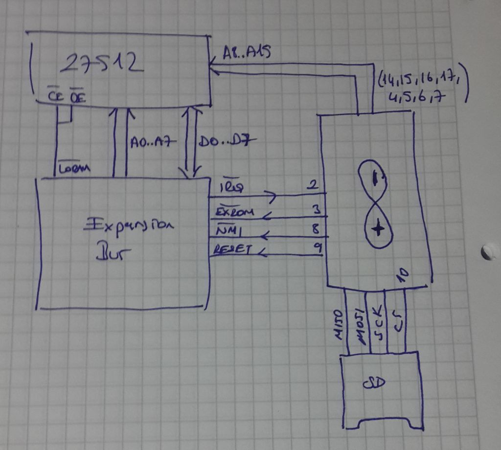
As you see, the three lines from the host system are called CLK, OP and OE. OE controls RAM output enable, and may be active-high or active-low according to whatever suits your circuit. OP determines what
OPCODE will appear on the data bus when it's floating and the pullup/pulldown resistors are doing their thing.
To put $20 on the bus, pull OP low. $20 is the opcode for JSR, a 3-byte, 6-cycle instruction.
To put $A8 on the bus, set OP high. $A8 is the opcode for TAY, a 1-byte, 2-cycle instruction. TAY is used as a kind of NOP.
OP also feeds an RC filter that drives /RESET. For that reason OP is kept high by default, brought low only for brief intervals (a few microseconds, perhaps). The exception is the case when a reset is desired. Then OP is held low for a much longer period (eg: 1 ms).
Here's a walkthrough of the boot sequence.
- After powerup, hold OP low long enough (1 ms or more, depending on the R and C) to ensure the CPU /RESET pin is also low. Using CLK we feed the CPU maybe 8 or 10 wakeup clock pulses, then stop. Next we bring OP high and wait 1 ms for /RESET to follow suit.
- Set OE false so the resistors have control of the data bus
- Put $20 on the bus (by pulling OP low). Deliver 7 clocks to execute the reset sequence. The PC = $2020 at this point.
Our first goal is to
get a known value into S (the stack pointer). To do that we load and run a position-independent program.
We repeat the following sequence 64 times:
- Put $A8 on the bus. Issue enough clocks to make PC= $EA9A-2. We're about to do a JSR. The address of the 3rd byte of the JSR instruction will get pushed.
- Put $20 on the bus. Issue 6 clocks. (PC = $2020, and $EA9A got pushed.)
- Put $A8 on the bus. Issue enough clocks to make PC= $EAA2-2. We're about to do a JSR. Again the address of the 3rd JSR instruction byte will get pushed.
- Put $20 on the bus. Issue 6 clocks. (PC = $2020, and $EAA2 got pushed.)
Page $01 is now full of repetitions of the following program (256 bytes total):
Code:
A2 EA LDX# $EA ;load X with the value $EA (even though we'd prefer $FF)
9A TXS ;transfer X to S
EA NOP ;the NOP is just padding. (It's easier if we deal with even numbers of bytes.)
;
A2 EA LDX# $EA ; again
9A TXS
EA NOP
; and so on
To proceed, we:
- Put $A8 on the bus. Issue enough clocks to make PC= $0100
- Set OE true so the RAM can be read
- issue 12 clocks -- enough to run the three-instruction sequence twice.
Now we know S = $EA. The strange procedure is necessary because S was initially unknown, and when we wrote the 256 bytes to Page 1 we began at an unknown location. So, when we later began execution at $0100 it's possible the first thing we did was to execute the LDX
operand as if it were an opcode! That's why the operand is chosen to coincide with a harmless, one-byte opcode ($EA). And that's why we issue enough clocks to run
two iterations of the sequence. If things get off on the wrong foot then the first iteration won't initialize S as desired.
Moving on: Presumably we have a more conventional program prepared -- the code which it's actually our goal to run.

As before, we'll push the code to RAM two bytes at a time. That means a pad byte will be needed if the program length isn't already an even number.
- Set OE false so the resistors can take control again
- Put $20 on the bus. Issue 6 clocks. PC= $2020. (NB: S= $E8. S's initial setting immediately got reduced by 2)
- Put $A8 on the bus. Issue clocks until PC= n-2. We're about to do a JSR. n -- the last 2 bytes of the program -- will get pushed
- Put $20 on the bus. Issue 6 clocks. PC = $2020.
- Put $A8 on the bus. Issue clocks until PC= n-2. We're about to do a JSR. n -- the next-to-last 2 bytes of the program -- will get pushed
- Put $20 on the bus. Issue 6 clocks. PC = $2020
- [ ... ]
- Put $A8 on the bus. Issue clocks until PC= n-2 We're about to do a JSR. n -- the first 2 bytes of the program -- will get pushed
- Put $20 on the bus. Issue 6 clocks. PC = $2020
Now the program is in place. All that remains is to run it:
- Put $A8 on the bus. Issue clocks until PC= the address of the first byte of program
- Set OE true so the RAM can be read
- issue enough clocks to run the program!

Footnote 1: one limitation (aside from speed) is that the initial setting of S -- $EA -- is lower than might be desired. A lower initial setting reduces the maximum program size. If that's a problem you can choose a different harmless, one-byte opcode as the operand for LDX. $FA (PLX) is acceptable. Or, choose $08 (PHP) and pad the end of your program so it exceeds 256 bytes and wraps you around.
Footnote 2: Obviously this bootup method needs to run a
lot of TAY instructions to increment PC as required. That's slow. But, FWIW, a slight increase in complexity can cut the number of TAY's approximately in half. Anytime you're about to...
- Put $20 on the bus. Issue 6 clocks. PC= $2020
- Put $A8 on the bus. Issue clocks until PC= [whatever]
...you may, if it helps (this requires checking on a per-case basis), do the following instead:
- Put $20 on the bus. Issue 1 clock. Put $A8 on the bus. Issue 5 clocks. PC= $A8A8
- Issue clocks until PC= [whatever]
Footnote 3:So far the idea hasn't been tested, and I'm concerned that perhaps /RESET itself exhibits variable latency. Although 65xx datasheets perhaps tacitly
imply there's a consistent number of clocks between /RESET going high and the fetch of the first instruction, there may in fact be some variability. This isn't something we can expect the datasheets to mention, as it's a detail that (almost) nobody cares about.
-- Jeff