6502.org Forum  Projects  Code  Documents  Tools  Forum
It is currently Thu Jun 20, 2024 12:32 pm

All times are UTC


Post new topic Reply to topic  [ 31 posts ]  Go to page Previous  1, 2, 3  Next
Author Message
PostPosted: Fri Aug 03, 2018 6:15 pm 
Offline
User avatar

Joined: Fri Aug 03, 2018 5:37 pm
Posts: 22
Has anyone successfully replaced the 6510 on a c64 with a W65C02S?

If so, is there a tutorial somewhere?

_________________
MOS


Top
 Profile  
Reply with quote  
PostPosted: Fri Aug 03, 2018 7:08 pm 
Offline

Joined: Mon May 21, 2018 8:09 pm
Posts: 1462
A complication here is that you have to emulate the 6510's built-in I/O ports, accessed through addresses $0000-1, which are not present in the plain 6502 or the later CMOS versions.

This isn't impossible to pull off, but it means you're building a daughterboard, not just plugging in a chip.


Top
 Profile  
Reply with quote  
PostPosted: Fri Aug 03, 2018 8:48 pm 
Offline
User avatar

Joined: Fri Dec 11, 2009 3:50 pm
Posts: 3366
Location: Ontario, Canada
Perhaps you'll be interested in the "6502" forum member Drass made out of a collection of 7400-series chips. The TTL CPU can masquerade as either a 6502/65C02 or as a 6510. It has two connectors that accept a ribbon cable attaching to an adapter which in turn plugs into the CPU socket of the host computer. Depending which connector you choose you can get the 6502/65C02 pinout or that of a 6510. :)

The (rather long) thread describing the project begins here: TTL 6502 Here I come. Last I heard the thing was running successfully at 20 MHz, with even faster tests soon to be undertaken. :shock:

Edit: at these speeds no ribbon cable is used; instead a purpose-built SBC attaches directly to the CPU.

-- Jeff

_________________
In 1988 my 65C02 got six new registers and 44 new full-speed instructions!
https://laughtonelectronics.com/Arcana/ ... mmary.html


Top
 Profile  
Reply with quote  
PostPosted: Sat Aug 04, 2018 3:21 am 
Offline
User avatar

Joined: Fri Aug 03, 2018 5:37 pm
Posts: 22
Ok, thanks! Looks complicated.

_________________
MOS


Top
 Profile  
Reply with quote  
PostPosted: Sat Aug 11, 2018 3:15 pm 
Offline
User avatar

Joined: Sun Oct 18, 2015 11:02 pm
Posts: 428
Location: Toronto, ON
Hello Rupy. If it will help, you can find a schematic for 6510 portion of the TTL CPU here.

A simpler alternative is to use a 65C22 VIA for the 6510 port. You still need a purpose-built daughter board, but it’s a more straight forward task. Don’t hesitate to ask for more details if you are interested.

_________________
C74-6502 Website: https://c74project.com


Top
 Profile  
Reply with quote  
PostPosted: Mon Aug 13, 2018 1:57 pm 
Offline
User avatar

Joined: Wed Aug 17, 2005 12:07 am
Posts: 1211
Location: Soddy-Daisy, TN USA
IIRC, the 6510 used in the C64 also has a different pinout than the 6502. So not only did it have some additional I/O installed, the pins won't match. So yeah...a daughercard or adapter would have to be constructed as well.

_________________
Cat; the other white meat.


Top
 Profile  
Reply with quote  
PostPosted: Mon Aug 13, 2018 3:33 pm 
Offline
User avatar

Joined: Fri Dec 12, 2008 10:40 pm
Posts: 1003
Location: Canada
I've put WDC65C02s in both my old OSI Superboard and my SIM-1 and they worked just dandy. I don't think there is a single CMOS chip in either of those systems. Perhaps the W65C02 is forgiving in that manner, but YMMV.

I did try the CMOS version of the 2114 RAM chips (TC5514) in the Superboard but that was not successful. On the other hand, I made a memory upgrade for the SYM-1 using an NEC D43256, which is a CMOS SRAM and it works fine, looking at the specs for though I'd expect it to be fine in any environment.

Has anyone tried a W65C02 in an Apple II?

_________________
Bill


Top
 Profile  
Reply with quote  
PostPosted: Mon Aug 13, 2018 3:44 pm 
Offline
User avatar

Joined: Wed Aug 17, 2005 12:07 am
Posts: 1211
Location: Soddy-Daisy, TN USA
BillO wrote:
Has anyone tried a W65C02 in an Apple II?


I've read that people have done that before. Although, I think one of the pins must be left unconnected.

Also, IIRC, the Apple IIc has a 65C02 in it. But I could be wrong on that one.

I have two of them. But I'm too lazy to crack the hood on them at the moment. lol

_________________
Cat; the other white meat.


Top
 Profile  
Reply with quote  
PostPosted: Mon Aug 13, 2018 6:02 pm 
Offline
User avatar

Joined: Fri Aug 30, 2002 1:09 am
Posts: 8459
Location: Southern California
cbmeeks wrote:
BillO wrote:
Has anyone tried a W65C02 in an Apple II?

I've read that people have done that before. Although, I think one of the pins must be left unconnected.

That's pin 1, which on the WDC part is a VP\ (vector pull not) output, rather than another ground. (Pin 21 remains a ground pin.)

Quote:
Also, IIRC, the Apple IIc has a 65C02 in it. But I could be wrong on that one.

Later IIe's had it. The IIc always used the 65C02.

_________________
http://WilsonMinesCo.com/ lots of 6502 resources
The "second front page" is http://wilsonminesco.com/links.html .
What's an additional VIA among friends, anyhow?


Top
 Profile  
Reply with quote  
PostPosted: Mon Aug 20, 2018 8:22 am 
Online
User avatar

Joined: Fri Nov 09, 2012 5:54 pm
Posts: 1397
Ruud Baltissen has something on his homepage about replacing a 6510 with a 65816.
He had used a 6526 for implementing that 6510 I\O port.

From the 6522 datasheets, it looks like the address on the bus has to be stable before the rising edge of PHI2 (what probably isn't the case because of how the VIC-II uses the bus).
From the 6526 datasheet, the signals on the bus have to be stable before the _falling_ edge of PHI2.


Top
 Profile  
Reply with quote  
PostPosted: Mon Aug 20, 2018 10:18 am 
Offline

Joined: Mon May 21, 2018 8:09 pm
Posts: 1462
But the VIC-II doesn't drive the 6502 address bus - it is the DRAM controller as well as the video controller.


Top
 Profile  
Reply with quote  
PostPosted: Mon Aug 20, 2018 11:01 am 
Offline

Joined: Tue Jul 24, 2012 2:27 am
Posts: 672
What do you mean? The VIC-II's reading & refreshing of the shared memory certainly implies it's driving the address pins & reading data. There's only 1 main bus in the system, with a short diversion to also let the VIC-II directly read the 4-bit color RAM in parallel.

_________________
WFDis Interactive 6502 Disassembler
AcheronVM: A Reconfigurable 16-bit Virtual CPU for the 6502 Microprocessor


Top
 Profile  
Reply with quote  
PostPosted: Mon Aug 20, 2018 2:39 pm 
Offline

Joined: Fri Apr 06, 2018 4:20 pm
Posts: 94
White Flame wrote:
What do you mean? The VIC-II's reading & refreshing of the shared memory certainly implies it's driving the address pins & reading data. There's only 1 main bus in the system, with a short diversion to also let the VIC-II directly read the 4-bit color RAM in parallel.


The address lines on the 6510 and the VIC-II are both active and are independent of one another (the VIC-II only has 14 lines and can only see 16K at at time). They SHARE the bus, accessing it at different times. The VIC-II is the bus master, in that it can tell the processor to wait. The memory refresh being on the VIC is not related to the above except it affects timing (how long the VIC-II keeps control of the bus).

The address decoding goes through the PLA on the C64 as well, though you could conceive of a simpler system with 32K RAM, 16K ROM, and the remainder of the 64K for the video page and I/O (minus a few K for color RAM) and less I/O ports, that would not require such complex decoding.


Top
 Profile  
Reply with quote  
PostPosted: Tue Aug 21, 2018 7:20 am 
Online
User avatar

Joined: Fri Nov 09, 2012 5:54 pm
Posts: 1397
Starting to remember, that there had been something in the 64'er magazine (2/1994) about modifying a C64 to run at 2MHz.
See here and there.

The modification to the C64 was a rather big one, SRAM instead of DRAM etc.
CPU was a 6502A.
/LORAM, /HIRAM and /CHAREN were generated by 74LS74 flipflops which simply were written in parallel to RAM address $0001.
This isn't too compatible to the original C64, and of course the cassette port was no longer supported by this hardware.


Top
 Profile  
Reply with quote  
PostPosted: Mon Sep 03, 2018 7:11 pm 
Offline

Joined: Thu Aug 23, 2018 7:10 am
Posts: 89
Location: CyberBunker
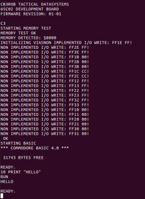
Attachment:
EMULATOR.png
EMULATOR.png [ 32.24 KiB | Viewed 3728 times ]
<-- emulator, more or less fully working basic, as-is ripped from the pet rom, unmodified. the emulator however thinks it has an NMOS 6502 cpu.


output of the real board: (WDC65C02, although the important part of the address decoding is hanging overboard on a rather ghetto soldered experiment board, but that's unlikely to be the cause as it does run other big chunks of code without failure)

2A *
2A *
2A *
20
43 C
4F O
4D M
4D M
4F O
44 D
4F O
52 R
45 E
20
42 B
41 A
53 S
49 I
43 C
20
34 4
2E .
30 0
20
2A *
2A *
2A *
0D
0A
0D
0A
0D <--- magically appearing extra $13 where the <space>NNNNN" BYTES FREE"$13 should be :P
0A


any 'nmos 6502' only stuff in microsoft/commodore basic i should be aware of? it all seems pretty vanilla code... nothing 'weird' or 'undocumented' except for the mnemonics those people used. (not just mickeysoft themselves, also most 'translations' and 'commented disassemblies' are quite creative with mnemonics, making up things like 'BE' or 'BNZ' themselves ;)

the 'not implemented i/o write' errors of the emulator actually is the bios trying to initialize the not-emulated vias, waayyyy before commodore basic comes into play.
cbm basic -itself- doesn't seem to do anything with locations it should not be touching, no single attempt to read or write to locations it has no business with.


Top
 Profile  
Reply with quote  
Display posts from previous:  Sort by  
Post new topic Reply to topic  [ 31 posts ]  Go to page Previous  1, 2, 3  Next

All times are UTC


Who is online

Users browsing this forum: No registered users and 11 guests


You cannot post new topics in this forum
You cannot reply to topics in this forum
You cannot edit your posts in this forum
You cannot delete your posts in this forum
You cannot post attachments in this forum

Search for:
Jump to: