6502.org Forum  Projects  Code  Documents  Tools  Forum
It is currently Thu Oct 31, 2024 11:14 pm

All times are UTC


Post new topic Reply to topic  [ 6 posts ] 
Author Message
PostPosted: Sun Sep 27, 2020 4:56 am 
Offline

Joined: Sat Sep 26, 2020 1:58 am
Posts: 13
I have a Sym-1 that won't boot and I believe it might be the original 2332 mask ROM. I've burned a 2732 EPROM with Supermon 1.1 and wired the jumpers for the CS, OE and A11 pins but it didn't work. After reading through some of the documentation it seems that pin 20 for U20 is tied through an AND gate with the reset circuit to set the reset vector on powerup. Aside from just building a 2332/2732 socket adapter, is there a way to set the jumpers to allow the use of a 2732 in U20?

Thanks!


Top
 Profile  
Reply with quote  
PostPosted: Sun Sep 27, 2020 7:36 pm 
Offline
User avatar

Joined: Fri Dec 11, 2009 3:50 pm
Posts: 3367
Location: Ontario, Canada
mipspro wrote:
is there a way to set the jumpers to allow the use of a 2732 in U20?
Welcome. :)

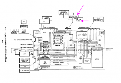
I had a quick look at the block diagram (below) contained in the SYM-1 Reference Manual located in our Synertek SYM-1 Resources page, and I gather that the jumpers would allow a 2332 or a 2532 to be fitted. But no word on 2732, although something may turn up if you dig a little deeper.

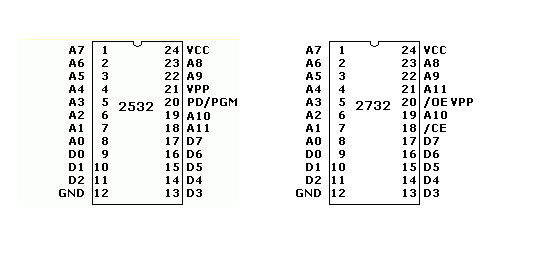
Otherwise, perhaps your best bet is to set the jumpers for 2532 then somehow make accommodation for the pinout differences with the 2732 you actually intend to use. Looks like you could attach the 2732's /CE and /OE together and drive them from pin 20 of the "2532" -- PD/PGM. That would be quite easy, mechanically, given how the pins line up.

If there's further troubleshooting to be done we're willing to help. It may be best to take your hunch about the 2332 being defective with a grain of salt.

Have fun, and keep us posted,

Jeff

edit: I didn't check the pinout for 2332. Possibly your task would be easier if the jumpers were set for it (rather than 2532).

Attachment:
Sym-1 block diagram.png
Sym-1 block diagram.png [ 88.62 KiB | Viewed 1106 times ]

Attachment:
2532-2732.png
2532-2732.png [ 4.85 KiB | Viewed 1106 times ]

_________________
In 1988 my 65C02 got six new registers and 44 new full-speed instructions!
https://laughtonelectronics.com/Arcana/ ... mmary.html


Top
 Profile  
Reply with quote  
PostPosted: Mon Sep 28, 2020 1:31 am 
Offline

Joined: Sat Sep 26, 2020 1:58 am
Posts: 13
Dr Jefyll wrote:
mipspro wrote:
is there a way to set the jumpers to allow the use of a 2732 in U20?
Welcome. :)

I had a quick look at the block diagram (below) contained in the SYM-1 Reference Manual located in our Synertek SYM-1 Resources page, and I gather that the jumpers would allow a 2332 or a 2532 to be fitted. But no word on 2732, although something may turn up if you dig a little deeper.

Otherwise, perhaps your best bet is to set the jumpers for 2532 then somehow make accommodation for the pinout differences with the 2732 you actually intend to use. Looks like you could attach the 2732's /CE and /OE together and drive them from pin 20 of the "2532" -- PD/PGM. That would be quite easy, mechanically, given how the pins line up.

If there's further troubleshooting to be done we're willing to help. It may be best to take your hunch about the 2332 being defective with a grain of salt.

Have fun, and keep us posted,

Jeff

edit: I didn't check the pinout for 2332. Possibly your task would be easier if the jumpers were set for it (rather than 2532).

Attachment:
Sym-1 block diagram.png

Attachment:
2532-2732.png


Thanks for the suggestion, however I tied /OE and /CS together on pin 20 and it still seems to not to want to boot. Also I tested the Sym-1's 6532 and 6502 in my Micro-KIM and neither works... My Micro-KIM's known working 6532 and 6502 don't work in the Sym-1 either... This board may have been damaged at some point in the past.... :cry:

I guess I will have to learn how to use a logic probe and Oscilloscope! I'll keep you guys posted.

Thanks again!


Top
 Profile  
Reply with quote  
PostPosted: Tue Sep 29, 2020 6:43 am 
Offline

Joined: Sat Sep 26, 2020 1:58 am
Posts: 13
Ok after a few hours of troubleshooting it's alive! In the course of testing I found that the 6502, 6532, both 6522s and 5 of 8 2114 rams were bad. After swapping out the chips with known good ones and testing the 2114s with an Arduino it seems to be working normally, save for 2 dead LED segments :cry:

Now to fix those displays and install RAE and BASIC roms!

Thanks again for the help!


Top
 Profile  
Reply with quote  
PostPosted: Tue Sep 29, 2020 3:59 pm 
Offline
User avatar

Joined: Fri Dec 11, 2009 3:50 pm
Posts: 3367
Location: Ontario, Canada
mipspro wrote:
it's alive!
Woo-hoo! :) Nice to hear.

Given the number of damaged chips, I wonder if somewhere in its past your poor SYM experienced a severe trauma, such as excessive voltage (or reverse polarity?) on the 5V supply. In fact I had something similar happen decades ago when 110 volts from the AC mains found its way into my pride and joy at the time, a radically modified KIM-1. NOT a happy thing -- I replaced dozens of chips! :cry:

As I recall, I very soon had to repair the machine a second time, and perhaps you will experience this, too. Seemingly there was a chip or two left teetering on the brink... kinda-sorta working, but destined for failure.

-- Jeff

_________________
In 1988 my 65C02 got six new registers and 44 new full-speed instructions!
https://laughtonelectronics.com/Arcana/ ... mmary.html


Top
 Profile  
Reply with quote  
PostPosted: Wed Sep 30, 2020 1:42 pm 
Offline

Joined: Sat Sep 26, 2020 1:58 am
Posts: 13
Dr Jefyll wrote:
mipspro wrote:
it's alive!
Woo-hoo! :) Nice to hear.

Given the number of damaged chips, I wonder if somewhere in its past your poor SYM experienced a severe trauma, such as excessive voltage (or reverse polarity?) on the 5V supply. In fact I had something similar happen decades ago when 110 volts from the AC mains found its way into my pride and joy at the time, a radically modified KIM-1. NOT a happy thing -- I replaced dozens of chips! :cry:

As I recall, I very soon had to repair the machine a second time, and perhaps you will experience this, too. Seemingly there was a chip or two left teetering on the brink... kinda-sorta working, but destined for failure.

-- Jeff


I think you might be right... This Sym-1 included the RAE and BASIC ROMs however from the look of the jumper settings they were never installed. Maybe the original owner incorrectly hooked up the power connector and damaged the board, then decided to just get a PET instead :D
In any case I'm just glad it's in a somewhat working order. Thanks again for the help!


Top
 Profile  
Reply with quote  
Display posts from previous:  Sort by  
Post new topic Reply to topic  [ 6 posts ] 

All times are UTC


Who is online

Users browsing this forum: No registered users and 2 guests


You cannot post new topics in this forum
You cannot reply to topics in this forum
You cannot edit your posts in this forum
You cannot delete your posts in this forum
You cannot post attachments in this forum

Search for:
Jump to: