Page 1 of 4
Issues with 6502?
Posted: Fri Jul 18, 2025 4:54 pm
by Niek6502
I was rebuilding my 6502-on-breadboard. Right now, it looks like my 6502 is misbehaving. I have the following simple test program:
Code: Select all
  lda #%00000000
loop:
  adc #%00000001
  sta $6000
  jmp loop
The compiled result is:
So it should initialize A to 0, then in the loop increment it with 1, and write A to address $6000.
What I see in a connected Arduino however is the following (with comments):
Code: Select all
  :
  fffc r 00      LSB of reset vector
  fffd r 80      MSB of reset vector
  8000 r a9      lda #%00000000
  8001 r 00
loop:
  8002 r 69      adc #%00000001
  8003 r 01
  8004 r 8d      sta $6000
  8005 r 00
  8006 r 60
  6000 w 60      --> It is writing $60 ???
  8007 r 4c      jmp loop
  8008 r 02
  8009 r 80
  8002 r 69      adc #%00000001
  8003 r 01
  8004 r 8d      sta $6000
  8005 r 00
  8006 r 60
  6000 w 60      --> it is again writing $60 ???
  :
Either my 6502 is misbehaving, or I am missing something basic (the latter is more likely...)
-Niek.
Re: Issues with 6502?
Posted: Fri Jul 18, 2025 5:00 pm
by 6502inside
What about other writes? Do those work?
Re: Issues with 6502?
Posted: Fri Jul 18, 2025 5:10 pm
by BigDumbDinosaur
I was rebuilding my 6502-on-breadboard. Right now, it looks like my 6502 is misbehaving. I have the following simple test program:
Code: Select all
  lda #%00000000
loop:
  adc #%00000001
  sta $6000
  jmp loop
...
Dunno if it is a factor, but you should clear carry before entering the loop. Also, unless using a 65C02, decimal mode following reset is an unknown and should be cleared with CLD.
Either my 6502 is misbehaving, or I am missing something basic (the latter is more likely...)
...or perhaps your test setup is misleading you.  Wouldn’t be the first time.
Re: Issues with 6502?
Posted: Fri Jul 18, 2025 5:22 pm
by Niek6502
Well, there is no other HW connected whatsoever (so only the 6502, an AT28C256 EEPROM and the Adruino). So I changed the code:
Code: Select all
  lda #%00000000
loop:
  adc #%00000001
  sta $4000
  sta $5432
  sta $6000
  sta $7abc
  jmp loop
Compiled:
Code: Select all
A9 00 69 01 8D 00 40 8D 32 54 8D 00 60 8D BC 7A 4C 02 80
The result:
Code: Select all
  fffc r 00    Reset vector
  fffd r 80
  8000 r a9      lda #%00000000
  8001 r 00
loop:
  8002 r 69      adc #%00000001
  8003 r 01
  8004 r 8d      sta $4000
  8005 r 00
  8006 r 40
  4000 w 40      --> weird - data is MSB of the address ?
  8007 r 8d      sta $5432
  8008 r 32
  8009 r 54
  5432 w 54      --> hm - seems so
  800a r 8d      sta $6000
  800b r 00
  800c r 60
  6000 w 60      --> yup, consistent
  800d r 8d      sta $7abc
  800e r bc
  800f r 7a
  7abc w 7a      --> very consistent
I wonder if I am not disabling the EEPROM at the moment of writing - it would likely still out put the last byte it was asked to. I do have A15 inverted and used as CEB on the EEPROM. I will single-step and at the moment of the "write" force CEB high.
Niek.
Re: Issues with 6502?
Posted: Fri Jul 18, 2025 5:38 pm
by BigEd
Welcome!
It can be useful to figure out a way to see if the EEPROM contents were mis-written, or are being mis-read.
If you'd swapped, or shorted, a couple of databus connections, you would find you're running code that isn't what you'd programmed. It's worthwhile to use a continuity tester (a multimeter) and check two things: that things which should be connected are connected; that things which are adjacent and should not be connected are indeed not connected.
Re: Issues with 6502?
Posted: Fri Jul 18, 2025 5:48 pm
by Dr Jefyll
Niek6502, I think perhaps your observations could be explained by the Arduino taking its sample at the wrong time. The sample should be taken during or at the end of the PHI2-high period. Instead I suspect the sampling occurs during or at the end of the PHI2-low period. (It would be a case of the test setup misleading you, as BDD suggested).
-- Jeff
Re: Issues with 6502?
Posted: Fri Jul 18, 2025 5:55 pm
by Niek6502
If you'd swapped, or shorted, a couple of databus connections, you would find you're running code that isn't what you'd programmed. It's worthwhile to use a continuity tester (a multimeter) and check two things: that things which should be connected are connected; that things which are adjacent and should not be connected are indeed not connected.
Agreed, will do. But the debugging is done with an Arduino looking at the address and data pins on the 6502, and the code read from the EEPROM appears OK (but I agree, it still doesn't rule out some short or line swap).
I am doing the A15 invert using a SN74LS04N - should I use a 74HC04 (could it be the invert is not "fast" enough, and the EEPROM is still showing the latched data on the bus)?
(Yes, this all is showing my newbie-ness, my apologies if my questions are too basic.)
Thanks all for indulging me.
-Niek.
Re: Issues with 6502?
Posted: Fri Jul 18, 2025 6:06 pm
by Niek6502
Niek6502, I think perhaps your observations could be explained by the Arduino taking its sample at the wrong time. The sample should be taken during or at the end of the PHI2-high period. Instead I suspect the sampling occurs during or at the end of the PHI2-low period. (It would be a case of the test setup misleading you, as BDD suggested).
The Arduino is set to sample the address and data bus when it detects a rising edge on PHI2:
Code: Select all
attachInterrupt(digitalPinToInterrupt(CLOCK),onClock,RISING);
(The "onClock" function is where it samples all the lines.) As I am running this test setup with a 555 timer as the clock (and about a second for each clock pulse), I can easily add a 50ms delay in sampling to make sure all has settled down.
Thanks for the suggestion! More things to try...
-Niek.
Re: Issues with 6502?
Posted: Fri Jul 18, 2025 6:12 pm
by GARTHWILSON
The Arduino is set to sample the address and data bus when it detects a rising edge on PHI2
Re: Issues with 6502?
Posted: Fri Jul 18, 2025 6:37 pm
by Niek6502
There's your problem. According to the data sheet, the write data does not begin to appear until tMDS time after phase 2 rises.
I also thought (after the suggestion) that this could be the issue of seeing things that weren't there. I introduced a delay of 50ms after PHI2 rises to do the sample of all the pins, and it still outputs the wrong byte:
Code: Select all
fffc r 1 00      Reset vector
fffd r 1 80
8000 r 1 a9      lda #%00000000
8001 r 1 00
8002 r 1 18      clc (at the suggestion of BDD - also, this is sa 65c02, so no CLD needed)
8003 r 1 69
8003 r 1 69      adc #%00000001
8004 r 1 01
8005 r 1 8d      sta $7abc
8006 r 1 bc
8007 r 1 7a
7abc w 0 7a      --> still seeing 7a instead of 01
800c r 1 00      ---> and here things go completely off the rails - it skipped 4 bytes ???
800c r 1 00
800d r 1 00
01fa w 0 00
01f9 w 0 80
01f8 w 0 0e
(Note that the "r/w" in the second column is reading the RWB pin, and the "0/1" after that is reading the CEB pin of the EEPROM.)
Especially with the program completely derailing (nonsensical addresses, weird read/write pin outputs etc), I don't think it is an issue with timing of the Arduino - it should still show some sensible program execution.
(Just to be clear, the setup is only a 6502, an EEPROM, and 1 74LS04 (to invert A15 to the CEB of the EEPROM), and the Arduino reading pins (all pins in the Arduino are set to INPUT mode.)
I will re-check _all_ connections and possible shorts between pins.
-Niek.
Re: Issues with 6502?
Posted: Fri Jul 18, 2025 7:31 pm
by Yuri
Seems really suspicious that it's saying it's writing the last value it saw that was being read. I suspect something with the Arduino code.
If you have a scope check to see what the values actually are on the data lines; if you don't have a scope, try setting it up with single stepping mode and use a multi-meter to check the data lines.
Or it might be worth while putting a 6522 or some other very simple device on there and seeing what happens when you write to that.
EDIT: It should be noted that it doesn't take a very fast clock to vastly outpace what the Arduino can reasonably react to.
Re: Issues with 6502?
Posted: Fri Jul 18, 2025 7:55 pm
by Niek6502
Just for completeness -
I tested all connections (testing from the 6502 pin to the exact breadboard "hole" where the removed EEPROM sits), and tested all pins and connection points for possible shorts, no joy.
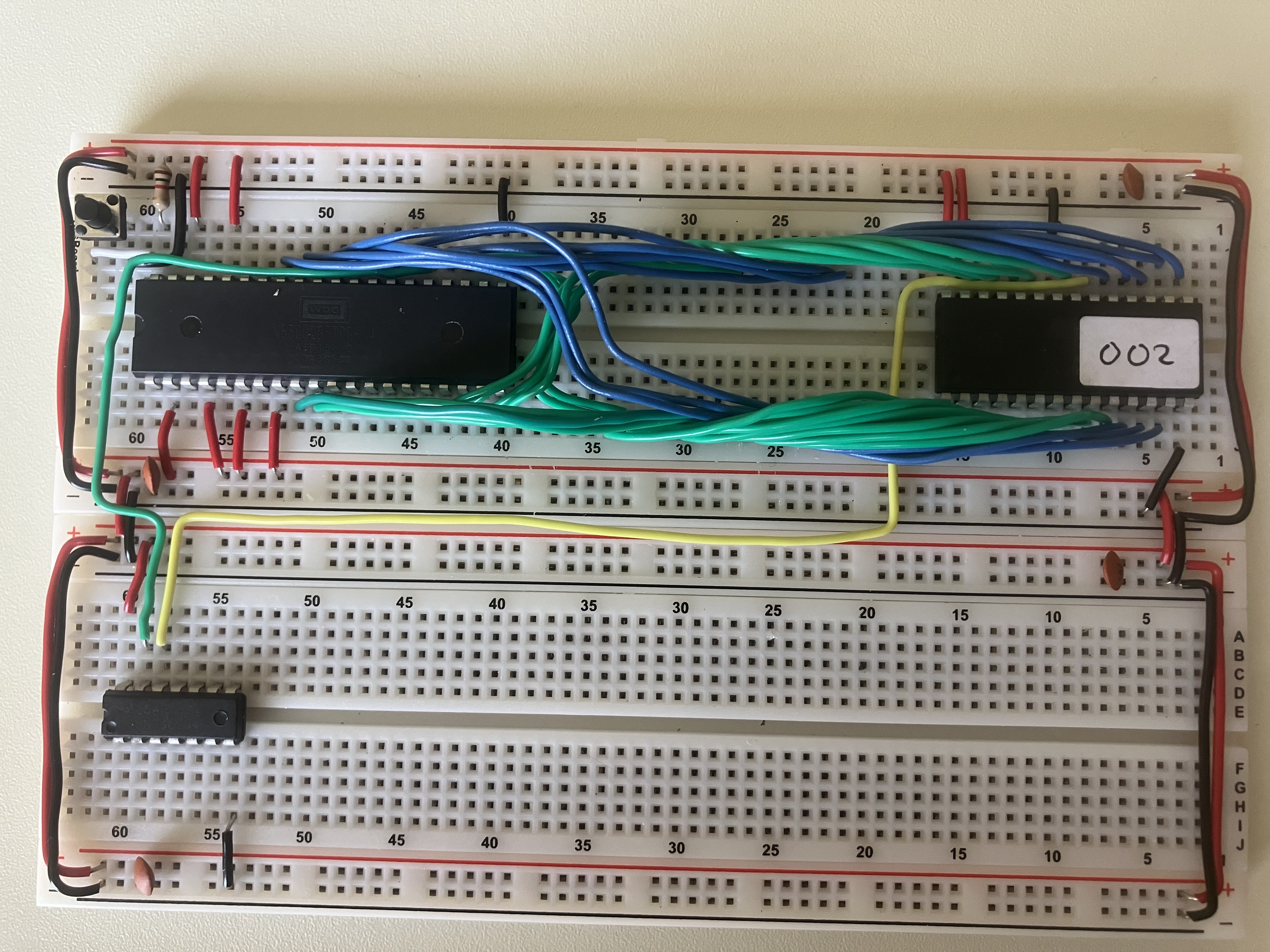
It looks like this:
http://www.qwertyboy.org/files/6502-001.jpg (the "002" sticker is because I have multiple EEPROMs so I can keep track of them).
Some/most will recognize a "Ben Eater" project. I wanted to change the layout of the components - the original had (on the top breadboard, left-to-right) 6502-EEPROM-SRAM, I want it to be 6502-SRAM-EEPROM (so removing/re-adding the EEPROM will be easier). That should explain the longer wires to the EEPROM - the SRAM will sit in between the 6502 and the EEPROM (once all is happier).
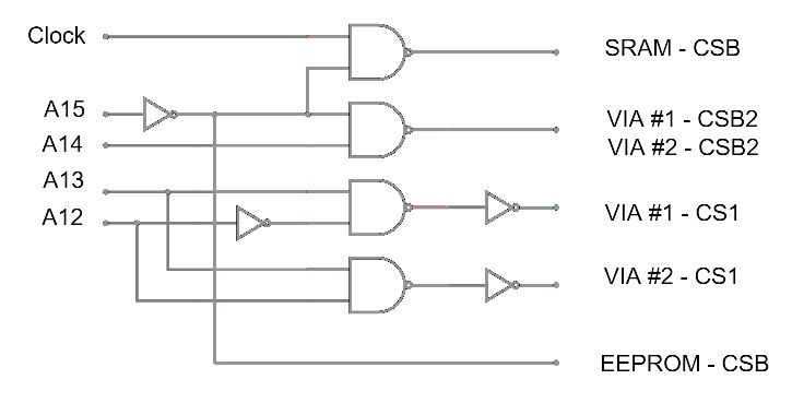
I also wanted to expand the computer with a second 6522 - that's why I am using an additional 7404 as part of the glue, as the glue will be more complex. See
http://www.qwertyboy.org/files/6502-002.jpg .
So I took the entire (working) setup apart and started anew, and somehow broke it. Guess it will take a shade longer to get it all working again (but then again, that's what hobbies are for - spending time on stuff you enjoy). I already had a second 65C02 on order for something else, should arrive this Monday, so I can easily rule that out.
-Niek.
Re: Issues with 6502?
Posted: Fri Jul 18, 2025 8:11 pm
by Niek6502
Seems really suspicious that it's saying it's writing the last value it saw that was being read. I suspect something with the Arduino code.
Suspicious, yes. But I don't think it is the Arduino showing wrong (or delayed) data. I did put in a 50ms delay in the Arduino code to have it read the lines 50ms after PHI2 goes high. And the results from my last test (a few posts up) shows that the program completely falls apart - that is not the Arduino simply being a bit late, it shows the CPU (for whatever reason) completely losing track of where it is.
If you have a scope check to see what the values actually are on the data lines; if you don't have a scope, try setting it up with single stepping mode and use a multi-meter to check the data lines.
I do have a scope, but it shows the same weird data.
Or it might be worth while putting a 6522 or some other very simple device on there and seeing what happens when you write to that.
Unless the data bus is behaving differently when another device is "listening", the fact I see wrong data on the bus will not make a 6522 fix things. But, being a newbie in this HW game (but with 40+ years of software development experience in networking, security, Linux kernel coding etc), I fully expect to have to put my foot in my mouth - I will try the 6522 option.
It should be noted that it doesn't take a very fast clock to vastly outpace what the Arduino can reasonably react to.
I would think the Arduino can keep up with a 1Hz clock though ...
Thanks for your post! More things to try...
-Niek.
Re: Issues with 6502?
Posted: Sat Jul 19, 2025 2:14 am
by Yuri
Or it might be worth while putting a 6522 or some other very simple device on there and seeing what happens when you write to that.
Unless the data bus is behaving differently when another device is "listening", the fact I see wrong data on the bus will not make a 6522 fix things.
Goal isn't to fix anything, it's to try and use some other device to rule out the Arduino being the issue.
In any event, you said you're using a modified Ben Eater design, all other things aside; it would be helpful to see a schematic of how you have things wired up, and possibly a photo of your build.
Re: Issues with 6502?
Posted: Sat Jul 19, 2025 6:30 am
by BigDumbDinosaur
The Arduino is set to sample the address and data bus when it detects a rising edge on PHI2...
...which, as Garth noted, will not work as expected. Try sampling right at the fall of the clock, as the buses will persist for a short time into Ø2 low. Also, make sure your test rig can keep up with your 65C02.
BTW, 74LS logic should not be used in new designs, especially when everything else is CMOS.
As I am running this test setup with a 555 timer as the clock...
A 555 timer sucks as a clock source for a 65C02, as it is grossly violating the recommended rise/fall times for Ø2. I suggest you run that 555 through a 74AC14 to fix up the signal. Keep the connections short and don’t be stingy with the bypass capacitors.
In any event, you said you're using a modified Ben Eater design, all other things aside; it would be helpful to see a schematic of how you have things wired up, and possibly a photo of your build.
Yes, a schematic (not in color!) would be very helpful, along with a clear photo of how you constructed your gadget.