Page 1 of 2
Possibly Dumb Question(s)
Posted: Sun Sep 03, 2023 5:47 pm
by anomie
Hi,
I built a Ben Eater kit with some tweaks based on info I found in the 6502 primer/here/searches/etc. (DS1813 for power-on reset and the reset button, a 74HC688 circuit in a thread here that was linked from the primer so I get the full 32k of RAM on the chip and my IO doesn't take so much address space, and I'm using a Rockwell R6551 for the serial instead of the WDC part, so I can actually check the bit to see if writes are done).
It all works fine so far, but I have IRQB unconnected on the R6551.
What I think I can do is:
- Put a pull-up on IRQB at the CPU
- Wire the IRQB pin on the cpu (between the pin and the pull-up) to the IRQB pin on the 6551
- Put a diode between the IRQB pin on W65C22S and the IRQB line made in the previous item - so that the VIA can pull that line low but can't actually drive it
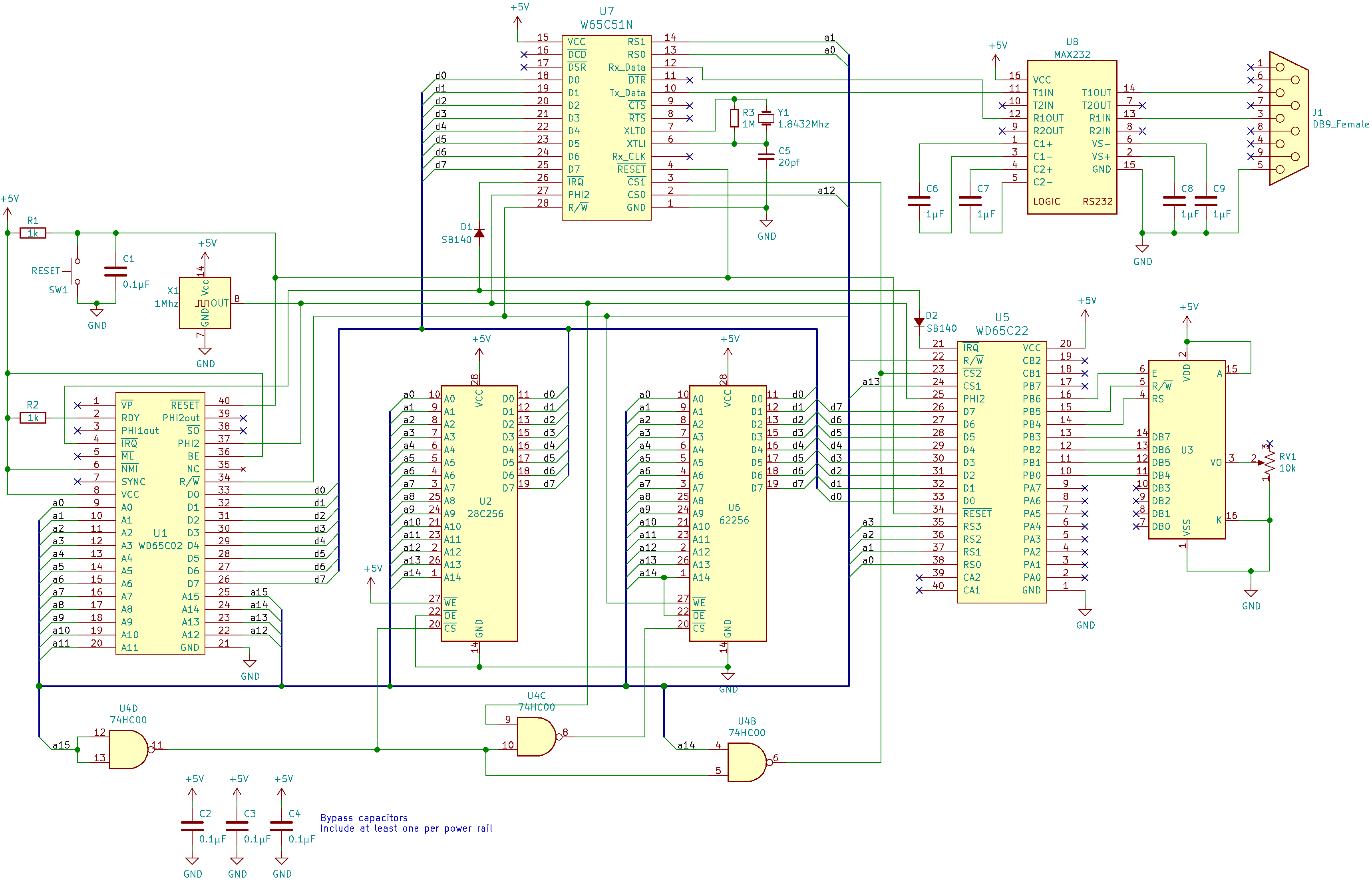
When I look at the schematic at eater.net (
https://eater.net/schematics/6502-serial.png) I don't see a pull-up, and I am not understanding why it doesn't have a pull-up.
So I'm wondering if I've missed something or if there's something I'd just know if I had more electronics experience that would make that make sense. If I am missing something, does what I'm missing mean I can't do what I outlined above to get my W65C22S & R6551 playing nice with each other re. IRQB?
Anything to look out for using the 'SB140' diode on that schematic? (I have some memory of threads talking about using some particular diode over another, for something, in a thread here somewhere and figured I may as well ask that too, if there's something that is for some reason better I can use, before I order some).
Re: Possibly Dumb Question(s)
Posted: Sun Sep 03, 2023 6:11 pm
by AndrewP
I think you're right, there is a pull-up missing IRQB. It also looks like the diode D2 is necessary because the W65C22S has a totem poll output on its IRQ but the diode D1 is unnecessary because W65C61N has an open drain IRQ.
Re: Possibly Dumb Question(s)
Posted: Sun Sep 03, 2023 7:40 pm
by Paganini
The Primer has a page about this. In particular, you're looking for the schematic that shows how to combine both open-drain and totem-poll IRQ sources in the same circuit:
You can skip the diodes.

Re: Possibly Dumb Question(s)
Posted: Sun Sep 03, 2023 8:04 pm
by anomie
You can skip the diodes.
That primer page is what I was reading when I decided I wanted to use a diode and a resistor. Specifically the "An AND-gate substitute ..." portion.
On the basis of "I'm running at 1MHz so I shouldn't run into the rising edge problem detailed there, and I don't really want to add another IC /just/ for this".
Re: Possibly Dumb Question(s)
Posted: Mon Sep 04, 2023 8:03 am
by BigDumbDinosaur
On the basis of "I'm running at 1MHz so I shouldn't run into the rising edge problem detailed there, and I don't really want to add another IC /just/ for this".
Be sure to use a small-signal Schottky for the blocking diode.
Also, I should mention that Mr. Eater omits some things that are needed to build a properly-working system.
Re: Possibly Dumb Question(s)
Posted: Mon Sep 04, 2023 1:27 pm
by anomie
Also, I should mention that Mr. Eater omits some things that are needed to build a properly-working system.
When I built the kit I didn't follow along with his videos, but pulled the datasheets for the parts and read through them. Partly because I felt like following along would mean I'd learn less. I had binged his videos before I ordered the kit, I'd at least seen them and had some context, so it's not like I put it together blind, but I feel like I learned more than if I'd sat there watching his videos and wired things by video rote, by sitting there with copies of the datasheets and figuring things out while I was doing it.
But it was also partly because I knew about things like his not putting a resistor on RDY in the videos, but putting one on in his schematic - and didn't want to run into something else like that if I could avoid it by reading datasheets. That he did that bothers me a bit.
It's also why I asked about the SB140 he put on that schematic, because I had the thought that he might have thrown on something that he thought should work and had handy (or maybe could easily source for some future kit, the serial kit didn't have any diodes in it) vs. a possibly more appropriate part.
So thank you, and now I will go looking for small-signal Schottky diodes.
Re: Possibly Dumb Question(s)
Posted: Mon Sep 04, 2023 3:45 pm
by BigDumbDinosaur
So thank you, and now I will go looking for small-signal Schottky diodes.
- bat85_npx.pdf
- BAT85 Small-Signal Schottky Diode
- (126.05 KiB) Downloaded 180 times
Re: Possibly Dumb Question(s)
Posted: Mon Sep 04, 2023 4:51 pm
by BigEd
Welcome, anomie!
Re: Possibly Dumb Question(s)
Posted: Sat Sep 09, 2023 2:22 pm
by anomie
I ordered a small pile of these after you linked this. They arrived yesterday and last night I wired everything up and it's working, at least to the point that the handler for the VIA timer interrupt I'd set up in my ROM still work fine. The plan for today is to write some code to actually use the 6551 interrupts.
The projects I've done in the past have all been kit-type "the components you need are already in the bag"; I found
this post of yours pretty illuminating - I think I at least now know what I should be thinking about in a spot like this in the future.
Thanks! I've been meaning to post something over in the general intro thread, I should probably get around to actually doing that.
Re: Possibly Dumb Question(s)
Posted: Sun Sep 10, 2023 5:40 pm
by anomie
I wrote a little test program, in phases, to test things out. It has the ACIA transmit and receive interrupts and the VIA timer 1 interrupt enabled, with the VIA interrupt firing about 60 times a second. I took two pages and used one for a circular buffer for characters coming in and the other for a circular buffer of characters to send out.
The interrupt handler checks all three possible interrupt causes and handles them appropriately. If it detects a timer interrupt I bump a count of the timer interrupts, and if masking that against a value results in zero, reads/increments/writes port B (so I can see it counting on the LEDs I have hooked up there, at a rate much slower than how often the timer interrupt actually fires).
After the setup code I fill the write buffer with "Interrupt Test ROM\r" and cli, then drop into a loop taking characters from the read buffer and dropping them into the write buffer.
That all appears to be working fantastically. I get the message in minicom, the LEDs appear to be firing at the rate they should be, and anything I type gets sent right back to me.
On a tiny oscilloscope I bought to have an oscilloscope to poke at this project with, the VIA pulls the line down slightly less than the ACIA does - which makes sense as a mix of 'they may pull to different lows anyway (and now I want to go check the datasheets on that) but there's also that diode in there on the VIA side'. Neat.
Re: Possibly Dumb Question(s)
Posted: Tue Sep 12, 2023 7:44 pm
by anomie
Right now I have exactly three non-output pins that aren't connected. I want to make sure I've got all inputs or potential inputs handled correctly.
Pins 8 & 10 on the MAX232:
pin 10 is 'DIN2' and the datasheet states "Internal Pull-Up resistors on DIN inputs ensures a high input when the line is high impedance" under "RS-232 Driver". So I think I'm good to just mark that as not connected on the schematic I'm making, is there any reason to do anything different?
pin 8 is 'RIN2' and the datasheet states 'An open or shorted to ground input results in a high output on ROUT' - I read this and think that might mean a no-connect is fine there too but then I start thinking things like 'well, you could just pull it high or low and if you did high it would make ROUT low and vice-versa' and I don't know this well so I'd like to understand if it matters at all and if so why.
The last one is RxC on the RS232, my reset code in the ROM means this is, by setting bit 4 in the control register to 0, usually an output. But every hardware reset will mean bit 4 is 1, making it an input for a very short time, and there's always the possibility I accidentally set the bit in code. So I want to pull it one way or the other - does it matter which way at all? If I tie low then I figure it'll have some small oscillating signal going through because normal operation/config by the software makes it an output clock, if I tie high then it'd just be high all the time, and I'd just have the current the resistor lets through going through during the hardware resets or if I accidentally set the bit (edit: or will it stay high, since the chip will try to go low, so I'd have some oscillation there either way?). So that makes me think I should probably just tie it high and call it done, but I keep waffling on all three of these because I'm a software guy and out of my safety-net land of "I'm doing software, in a nice non-production environment, and the worst that could happen is I rewrite some code" (I don't think I've had to worry about actually hurting hardware since back when you could still get a monitor that would do bad things if you set the frequency wrong in your video mode).
Maybe I'm overthinking all this, if that's the case let me know that too.
Re: Possibly Dumb Question(s)
Posted: Wed Sep 13, 2023 8:37 pm
by BigDumbDinosaur
Pins 8 & 10 on the MAX232:
pin 10 is 'DIN2'...
From which data sheet did you get that designation? The designation of pin 10 on the genuine Maxim data sheet is T2IN. Reason I ask is I’m wondering if you got a non-authoritative data sheet that may have errors. Here’s the genuine data sheet:
...and the datasheet states "Internal Pull-Up resistors on DIN inputs ensures a high input when the line is high impedance" under "RS-232 Driver". So I think I'm good to just mark that as not connected on the schematic I'm making, is there any reason to do anything different?
The internal pull-ups are pretty weak, in my opinion, and if a Tx input is to be floated, should be supplemented with a 4.7K resistor to VCC to make the Tx input less noise-sensitive. Being pulled up in this fashion results in the Tx output being in a continuous MARK condition. Despite being unnecessary, there is no harm in having the external pull-up in the circuit for a “live” Tx channel, other than some increased loading on the corresponding UART output.
pin 8 is 'RIN2' and the datasheet states 'An open or shorted to ground input results in a high output on ROUT' - I read this and think that might mean a no-connect is fine there too but then I start thinking things like 'well, you could just pull it high or low and if you did high it would make ROUT low and vice-versa' and I don't know this well so I'd like to understand if it matters at all and if so why.
The MAX232 Rx channels, like the Tx channels, are inverting. Although intended to react to typical TIA-232 levels, the MAX’s Rx inputs are actually TTL-compatible and therefore see anything above +2.4 volts as a valid SPACE, and anything below +0.8 volts as a valid MARK. This arrangement makes the MAX232 less fussy about input signal levels on the TIA-232 side, but also increases noise sensitivity.
Each Rx input is internally tied to ground through a 5K resistor, which causes the input to think it is seeing a MARK condition. However, a floating Rx input will be easily disturbed by noise. For that reason, I recommend that unused Rx channel inputs be pulled up to VCC through no more than 1K of resistance. This will keep the input well above the “no man’s land” input threshold and result in the corresponding Rx output continuously being at logic 0, since the corresponding input will continuously be at SPACE.
Lastly, my most recent POC units used MLCCs for the charge pump capacitors. I used to use tantalums, but decided to see if the less-expensive MLCCs would work okay...which they do. Pay attention to layout: the charge pump caps should be as physically close to the MAX232 as possible. Also, be sure to bypass the MAX’s VCC with a parallel combination of a 1 µF MLCC and 100 µF low-ESR electrolytic, both caps being in close physical proximity to the MAX232.
Re: Possibly Dumb Question(s)
Posted: Wed Sep 13, 2023 9:20 pm
by anomie
From which data sheet did you get that designation? The designation of pin 10 on the genuine Maxim data sheet is T2IN. Reason I ask is I’m wondering if you got a non-authoritative data sheet that may have errors.
My chip has a TI logo on it, unless I’m really dumb and that’s not a TI logo. I am pretty sure I googled "MAX232ECN" and ended up downloading it from the TI website - the datasheet I’ve been working from definitely purports to be a TI datasheet.
Re: Possibly Dumb Question(s)
Posted: Wed Sep 13, 2023 9:54 pm
by anomie
That pic shows in my phone with the chip, and therefore the text on it, horizontal - so I guess my phone has been lying to me about what image actually look like. Sorry about that.
The internal pull-ups are pretty weak, in my opinion, and if a Tx input is to be floated, should be supplemented with a 4.7K resistor to VCC to make the Tx input less noise-sensitive. Being pulled up in this fashion results in the Tx output being in a continuous MARK condition. Despite being unnecessary, there is no harm in having the external pull-up in the circuit for a “live” Tx channel, other than some increased loading on the corresponding UART output.
Ok - I’ll pull it up through a 3.3k “for now” and lay my hands on some 4.7k. I bought a small pile of 3.3k and stopped using the 1ks that came with the kit as the primer advises a 3.3k for everything the kit schematic uses a 1k for. Which means …
For that reason, I recommend that unused Rx channel inputs be pulled up to VCC through no more than 1K of resistance. This will keep the input well above the “no man’s land” input threshold and result in the corresponding Rx output continuously being at logic 0, since the corresponding input will continuously be at SPACE.
… I definitely have a 1k I can use for this right now.
Lastly, my most recent POC units used MLCCs for the charge pump capacitors. I used to use tantalums, but decided to see if the less-expensive MLCCs would work okay...which they do. Pay attention to layout: the charge pump caps should be as physically close to the MAX232 as possible. Also, be sure to bypass the MAX’s VCC with a parallel combination of a 1 µF MLCC and 100 µF low-ESR electrolytic, both caps being in close physical proximity to the MAX232.
I currently have the caps as close as the breadboard will let me but with only a 1 µF on VCC - which is how it is in the circuit in the datasheet I have. I definitely appreciate the advice, thank you!
Re: Possibly Dumb Question(s)
Posted: Thu Sep 14, 2023 7:18 am
by BigEd
(Inadvertently rotated images are a common problem on boards like these: I think it's because rotation can be done either by metadata or by pixel shuffling. Also, the image file might contain preview images in addition to the full size one. In any case, if it bothers you, using any desktop tool to rotate the image a few times will usually deliver an image file that suits. There might also be online tools which could do it.)