Page 1 of 2
1Khz Square wave - how much is too much different?
Posted: Tue Jul 12, 2022 1:11 am
by decuser
All,
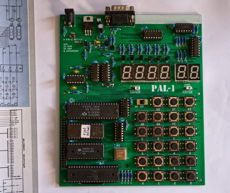
I'm new to 6502 programming. I bought a PAL-1 and I'm learning about 6502 programming and microprocessors. In the process, I found and read Don Lancaster's Micro Cookbooks... great books for folks like me, who never did any hardware or low level programming, btw. Anyway, one of the problems he presents (Discovery Module #4 - Audio Tone) requires the programmer to code up a 500us Low, 500us High square wave to fake an audio tone (it's not a sine wave, but it'll do). So I coded it up and ran it. Interestingly, it ran 500.25us low and 500.50us high. Here's my code and logic:
The flow was to:
Clear the decimal flag
Teach the port PB0 to be output
LOOP:
Output LO
Delay 491us
Output HI
Delay 491us
The Code:
Code: Select all
0200 D8	              CLD       ; clear decimal mode
0201 A9 01	              LDA #$01  ; prepare to set PB0 to output
0203 8D 03 17               STA $1703 ; set PB0
0206 A9 00	  GOLO:  LDA #$00  ; prepare to set PB0 LO
0208 8D 02 17	      STA $1702 ; set PB0 LO
020B A2 62	              LDX #$62  ; set counter to 62 hex
020D CA		   D1:      DEX       ; decrement the counter
020E D0 FD	              BNE D1    ; we there yet?
0210 4C 13 02	       JMP GOHI  ; yup, GOHI
0213 A9 01	   GOHI:  LDA #$01  ; prepare to set PB0 HI
0215 8D 02 17	      STA $1702 ; set PB0 HI
0218 A2 62	              LDX #$62  ; set counter to 62 hex
021A CA		    D2:     DEX       ; decrement the counter
021B D0 FD	              BNE D2    ; we there yet?
021D 4C 06 02	      JMP GOLO  ; yup, GOLO
0220 XX
There are 9 cycles of instructions - JMP (3), LDA (2), STA (4) between each delay loop (D1 and D2).
The desired cycle time for the square wave is 500us LO and 500us HI. So, the delay between states needs to be 500 - 9 cycles = 491us.
The delay loops use 5N - 1 cycles for the loop (5 cycles for each time through save the last, which only takes 4... DEX (2), BNE (3 for branching, 2 for not branching). Setup of the loop takes 2 cycles - LDX (2). So, each loop takes 5N+1 cycles.
Setting 5N+1 = 491 (the desired delay in us), N=98 (62H).
My question is - should I expect to get exactly 500us hi and 500us lo and if so, what kinds of things could be causing the discrepancy?
Re: 1Khz Square wave - how much is too much different?
Posted: Tue Jul 12, 2022 1:37 am
by BigDumbDinosaur
I'm new to 6502 programming.
Welcome to 6502 land.
I bought a PAL-1...read Don Lancaster's Micro Cookbooks...requires the programmer to code up a 500us Low, 500us High square wave to fake an audio tone (it's not a sine wave, but it'll do). So I coded it up and ran it. Interestingly, it ran 500.25us low and 500.50us high.
You didn't say what your Ø2 (primary clock) frequency is or how it is being generated. It may not be exactly what it should be. Hence the execution speed of the program will vary by a small amount from the theoretical.
In your code, you have:
Code: Select all
0210 4C 13 02          JMP GOHI  ; yup, GOHI
0213 A9 01      GOHI:  LDA #$01  ; prepare to set PB0 HI
The JMP GOHI instrution isn't necessary, as when the GOLO loop ends the MPU will "fall through" to GOHI. Try taking JMP GOHI out of there and observing what happens. If the frequency is too high, try adding a NOP in place of JMP GOHI to slightly slow down the program. NOP takes two Ø2 cycles to complete vs. three for JMP.
Re: 1Khz Square wave - how much is too much different?
Posted: Tue Jul 12, 2022 1:37 am
by BillO
Have you checked the CPU clock is exactly 1MHz?
Also, I believe it should be 5n-1 = 491, or n=98.4. So setting it to 98 should actually make your half cycle time .25us too fast, not too slow. This is what makes me think the clock might not be exactly 1MHz.
Not sure why low does not match high though.
As for me, I think your results are good enough for a computer of this type.
Re: 1Khz Square wave - how much is too much different?
Posted: Tue Jul 12, 2022 1:45 am
by BillO
The JMP GOHI instrution isn't necessary, as when the GOLO loop ends the MPU will "fall through" to GOHI. Try taking JMP GOHI out of there and observing what happens. If the frequency is too high, try adding a NOP in place of JMP GOHI to slightly slow down the program. NOP takes two Ø2 cycles to complete vs. three for JMP.
This would throw off the timing off a bit. Even if you put in a NOP you would have a difference of 1us between high and low.
Re: 1Khz Square wave - how much is too much different?
Posted: Tue Jul 12, 2022 4:28 am
by Dr Jefyll
Welcome! Those I/O addresses seem familiar to me. By any chance are you running the code on a KIM-1?

I haven't counted up your clock cycles, but I did reformat your code slightly, and it's apparent that the HI loop and the LO loop have virtually identical instructions. (BDD, I'm sure the purpose of the "unneccessary" JMP GOHI is to waste 3 cycles and
keep the two loops identical, timing-wise.)
Code: Select all
0200 D8	            CLD       ; clear decimal mode
0201 A9 01	         LDA #$01  ; prepare to set PB0 to output
0203 8D 03 17         STA $1703 ; set PB0

0206 A9 00	  GOLO:  LDA #$00  ; prepare to set PB0 LO
0208 8D 02 17	      STA $1702 ; set PB0 LO
020B A2 62	         LDX #$62  ; set counter to 62 hex
020D CA		   D1:   DEX       ; decrement the counter
020E D0 FD	         BNE D1    ; we there yet?
0210 4C 13 02	      JMP GOHI  ; yup, GOHI

0213 A9 01	   GOHI: LDA #$01  ; prepare to set PB0 HI
0215 8D 02 17	      STA $1702 ; set PB0 HI
0218 A2 62	         LDX #$62  ; set counter to 62 hex
021A CA		    D2:  DEX       ; decrement the counter
021B D0 FD	         BNE D2    ; we there yet?
021D 4C 06 02	      JMP GOLO  ; yup, GOLO
0220 XX
Since the number of clock cycles in the HI loop is the same as that in the LO loop, I'm inclined to suspect that the apparent asymmetry is just a measurement error. By what means did you determine that it ran 500.25us low and 500.50us high?
BTW, if it is indeed a KIM-1 then the clock rate is 1 MHz. And a discrepancy of .25 us between the HI loop and the LO represents a
fraction of one clock cycle, which seems highly dubious. One more reason to suspect some sort of issue with how the measurements were done.
-- Jeff
Re: 1Khz Square wave - how much is too much different?
Posted: Tue Jul 12, 2022 11:53 am
by HansO
It looks like the regulars here do now know the PAL-1 system.
The PAL-1, a small SBC, is a clone of the MICRO-KIM by Vince Briel and as such a KIM-1 clone with 6532 RIOT instead of the 6530 RRIOT.
Can be expanded with motherboard, memory, second RIOT, KIM tape I/O etc.
Well documented, affordable and being a KIM-1, all KIM-1 software and documentation is applicable.
For software it is a KIM-1, original ROMs, same interfaces (bit banged keypad/LEDs and serial I/O).
Available as kit on Tindie, enthusiastic users on twitter and groups.io.
The clock is made with a 1 MHz can oscillator, the KIM-1 has a crystal of 1 MHz.
Re: 1Khz Square wave - how much is too much different?
Posted: Tue Jul 12, 2022 1:33 pm
by decuser
Welcome! Those I/O addresses seem familiar to me. By any chance are you running the code on a KIM-1?
I haven't counted up your clock cycles, but I did reformat your code slightly, and it's apparent that the HI loop and the LO loop have virtually identical instructions. (BDD, I'm sure the purpose of the "unneccessary" JMP GOHI is to waste 3 cycles and
keep the two loops identical, timing-wise.)
...snip
Since the number of clock cycles in the HI loop is the same as that in the LO loop, I'm inclined to suspect that the apparent asymmetry is just a measurement error. By what means did you determine that it ran 500.25us low and 500.50us high?
BTW, if it is indeed a KIM-1 then the clock rate is 1 MHz. And a discrepancy of .25 us between the HI loop and the LO represents a
fraction of one clock cycle, which seems highly dubious. One more reason to suspect some sort of issue with how the measurements were done.
-- Jeff
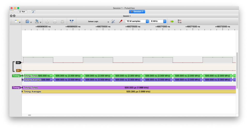
Yes, your analysis is correct. The JMP "eats" 3 cycles to keep the two identical and make them both 500us with a 1Mhz clock. It's a PAL-1, which is a clone of a KIM-1, with a can oscillator as Hans points out below, that supposedly clocks at 1Mhz. I'm inclined to think it might be measurement error. I used a 10 dollar 8 channel usb logic analyzer and just believed it cuz it seemed pretty accurate when I was looking at the microsecond level. I've got a Rigol DS1054Z. I'll hook that up and see how things look... and I'll read up on the logic analyzer specs (Saelae clone from China, I think), maybe fractions of microseconds at 1Mhz is beyond its limits somehow.
Will
Re: 1Khz Square wave - how much is too much different?
Posted: Tue Jul 12, 2022 1:42 pm
by decuser
It looks like the regulars here do now know the PAL-1 system.
And a beautiful thing it is, too! Hi Hans. Yours looks so much cooler than mine

. I'm off to checking measurement error cuz I'm pretty sure the code's ok (not stylewize, but cyclewize). I will also do a quick rewrite with a subroutine to clarify what's going on, the repeated code and synchronizing JMP are sloppy and arcane at the same time. They do the job and illustrate necessity, but there's a clearer way.
Re: 1Khz Square wave - how much is too much different?
Posted: Tue Jul 12, 2022 2:22 pm
by BillO
Also check the oscillator on the PAL-1.
Your code should give you half cycle period of 498us and a frequency of ~1004 KHz if the oscillator is exactly 1.0000 +/- 0.00005 MHz
In any case 498us is within 0.4% of your goal. What precision are you after?
Re: 1Khz Square wave - how much is too much different?
Posted: Tue Jul 12, 2022 4:06 pm
by hoglet
Your code should give you half cycle period of 498us and a frequency of ~1004 KHz if the oscillator is exactly 1.0000 +/- 0.00005 MHz
In any case 498us is within 0.4% of your goal. What precision are you after?
The code looks correct to me for 500us:
Code: Select all
0213 A9 01      GOHI: LDA #$01  ; (2)
0215 8D 02 17         STA $1702 ; (4)
0218 A2 62            LDX #$62  ; (2)
021A CA          D2:  DEX       ; (98 * 2)
021B D0 FD            BNE D2    ; (98 * 3 - 1)
021D 4C 06 02         JMP GOLO  ; (3)
                                  ---
                                  500
                                  ---
Any error here is most likely a measurement error; sampling at 1MHz is not nearly fast enough.
Even using a scope can be problematic, but it seems the Rigol can be quite accurate if you use it correctly:
http://nerdralph.blogspot.com/2015/07/r ... uracy.html
Re: 1Khz Square wave - how much is too much different?
Posted: Tue Jul 12, 2022 4:20 pm
by decuser
What I find interesting is that the clock signal is dead on and seems to be measured accurately, whereas the hi/lo is off...
Re: 1Khz Square wave - how much is too much different?
Posted: Tue Jul 12, 2022 4:23 pm
by BillO
Your code should give you half cycle period of 498us and a frequency of ~1004 KHz if the oscillator is exactly 1.0000 +/- 0.00005 MHz
In any case 498us is within 0.4% of your goal. What precision are you after?
The code looks correct to me for 500us:
Code: Select all
0213 A9 01      GOHI: LDA #$01  ; (2)
0215 8D 02 17         STA $1702 ; (4)
0218 A2 62            LDX #$62  ; (2)
021A CA          D2:  DEX       ; (98 * 2)
021B D0 FD            BNE D2    ; (98 * 3 - 1)
021D 4C 06 02         JMP GOLO  ; (3)
                                  ---
                                  500
                                  ---
Any error here is most likely a measurement error; sampling at 1MHz is not nearly fast enough.
Even using a scope can be problematic, but it seems the Rigol can be quite accurate if you use it correctly:
http://nerdralph.blogspot.com/2015/07/r ... uracy.html
The main loops need to be 491us, each loop takes 5n-1 cycles:
Therefore
5n-1 = 491
5n=491+1
5n=492
n=98.4
He used n=98 so he will have 489us loops. He came up with 489 because he originally wrote 5n+1=491 instead of 5n-1=491.
Edit: Ahh, okay .. form what you did I see another error he made that exactly cancels out the other error. It turns out his loop do need to be 489us because it looks like he forgot to account the the LDX instruction such that there is actually 11us outside the loops, not 9us. It's nice when two wrongs make a right. LOL!. All's good.
Re: 1Khz Square wave - how much is too much different?
Posted: Tue Jul 12, 2022 4:49 pm
by decuser
The math again:
GOLO: LDA (2)
STA (4)
Delay (491)
' Delay Loop:
LDX (2)
DX: DEX (2)
BNE (3 or 2)
JMP (3)
GOHI: LDA (2)
STA (4)
Delay (491)
So, just focusing on the delay loop:
2 for LDX
5 for each iteration (except for the last, which is 4)
This is 2 + 5N-1, or 5N+1...
Between each delay, there are 9 cycles - JMP (3), LDA (2), and STA (4).
So, if 9 cycles are eaten by overhead, 500-9 = 491.
So, 5N+1=491, and N=98, or 62H.
Then:
Setup of output port happens once, then...
GOLO: LDA (2) STA (4) +
Setup delay counter: LDX (2) +
Delay: (5 * 98) - 1 => (489) +
Change State to HI - JMP (3)
GOHI: LDA (2) STA (4) +
Setup delay counter: LDX (2) +
Delay: (5 * 98) - 1 => (489) +
Change State to LO - JMP (3)
------------------
6 + 2 + 489 + 3 = 500
6 + 2 + 489 + 3 = 500
Re: 1Khz Square wave - how much is too much different?
Posted: Tue Jul 12, 2022 7:04 pm
by BillO
My mistake. I should read better. I was counting the LDX in the overhead as only the DEX and BNE are actually in the loop.
BTW, the two wrongs I mentioned in my previous post were mine.
Re: 1Khz Square wave - how much is too much different?
Posted: Tue Jul 12, 2022 7:28 pm
by decuser
Ha. I kept hoping it was the code! That’d be the easiest to fix. Meanwhile. I’m gonna keep digging!