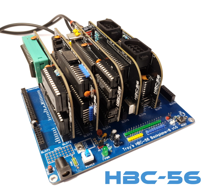
HBC-56 project (65C02 + TMS9918A on a backplane)
Posted: Mon May 23, 2022 1:44 am
Rather than start a new thread for each update on this project, I've decided to create a single thread and update it as required. This is that thread.
Background
This is my second homebrew project after first completing a Ben Eater inspired SAP-1ish on a breadboard. Dipped my toe in 65C02 assembly working on some Commander X16 projects, so decided to do a 65C02 next. Loved the idea of a backplane where I can easily add/replace components of the build at will. I also have a soft spot for the TMS9918A having grown up with a TI-99/4A. So that was my starting point. (Yes, I'm quite a newbie at this - but have a very extensive background in software).
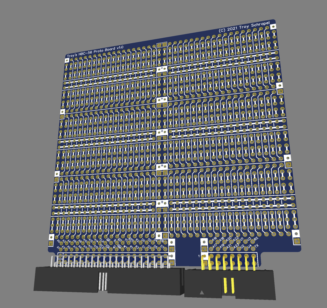
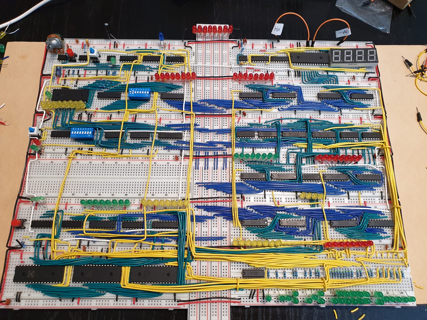
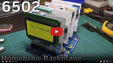
I started out building the project on breadboards, but then designed a backplane and custom proto card to start the build proper. I started out with a graphics LCD:
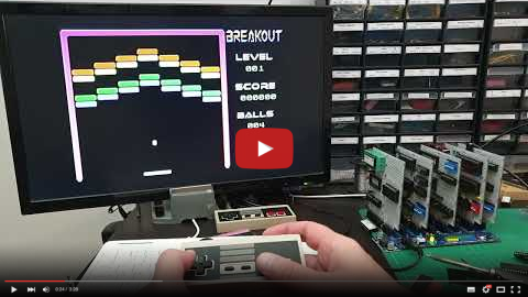
Then built the TMS9918A card and added support for a NES controller:
It was around this point I started working on the emulator. For this, I wrote my own 65C02 and TMS9918A emulator libraries and built both a desktop and web-based version. You can try the latest web version here (requires keyboard): https://visrealm.github.io/hbc-56/emulator/wasm
Not long after that, I was contacted by PCBWay who were keen to supply me with PCBs in return for mentioning them (nothing more than that). This surprised me as my project / YouTube, etc. has very few followers, but I decided to go ahead anyway. This gave me the perfect opportunity to design custom PCBs to replace the old hand-wired ones.
The brings me to the present day where I've started building out some of these new cards and documenting the process in video form. It's not all smooth-sailing and you might get something out of these. If you're interested in TMS9918A development, I'm planning to do some videos on that specifically soon (probably after the card build series).
Updates
28 May 2022
The new RAM/ROM card. It contains 64KB RAM + 32KB ROM with runtime-configurable selection of RAM or ROM in 4KB pages.

23 May 2022
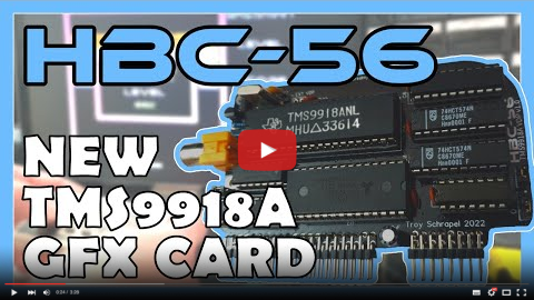
Video covering the schematic, PCB design, assembly and testing of my new TMS9918A display card
16 May 2022
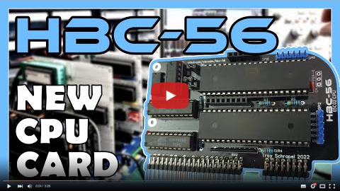
Video covering the schematic, PCB design, assembly, diagnosis, repair and testing of my new 65C02 CPU card
Project links
GitHub: https://github.com/visrealm/hbc-56
YouTube: https://www.youtube.com/playlist?list=P ... NCxNknMrcR
Emulator (live online instance, requires keyboard) : https://visrealm.github.io/hbc-56/emulator/wasm
Hackaday: https://hackaday.io/project/180904-hbc- ... -backplane
Background
This is my second homebrew project after first completing a Ben Eater inspired SAP-1ish on a breadboard. Dipped my toe in 65C02 assembly working on some Commander X16 projects, so decided to do a 65C02 next. Loved the idea of a backplane where I can easily add/replace components of the build at will. I also have a soft spot for the TMS9918A having grown up with a TI-99/4A. So that was my starting point. (Yes, I'm quite a newbie at this - but have a very extensive background in software).
I started out building the project on breadboards, but then designed a backplane and custom proto card to start the build proper. I started out with a graphics LCD:
Then built the TMS9918A card and added support for a NES controller:
It was around this point I started working on the emulator. For this, I wrote my own 65C02 and TMS9918A emulator libraries and built both a desktop and web-based version. You can try the latest web version here (requires keyboard): https://visrealm.github.io/hbc-56/emulator/wasm
Not long after that, I was contacted by PCBWay who were keen to supply me with PCBs in return for mentioning them (nothing more than that). This surprised me as my project / YouTube, etc. has very few followers, but I decided to go ahead anyway. This gave me the perfect opportunity to design custom PCBs to replace the old hand-wired ones.
The brings me to the present day where I've started building out some of these new cards and documenting the process in video form. It's not all smooth-sailing and you might get something out of these. If you're interested in TMS9918A development, I'm planning to do some videos on that specifically soon (probably after the card build series).
Updates
28 May 2022
The new RAM/ROM card. It contains 64KB RAM + 32KB ROM with runtime-configurable selection of RAM or ROM in 4KB pages.
23 May 2022
Video covering the schematic, PCB design, assembly and testing of my new TMS9918A display card
16 May 2022
Video covering the schematic, PCB design, assembly, diagnosis, repair and testing of my new 65C02 CPU card
Project links
GitHub: https://github.com/visrealm/hbc-56
YouTube: https://www.youtube.com/playlist?list=P ... NCxNknMrcR
Emulator (live online instance, requires keyboard) : https://visrealm.github.io/hbc-56/emulator/wasm
Hackaday: https://hackaday.io/project/180904-hbc- ... -backplane