Page 1 of 2
Clock generation for 6502
Posted: Tue Dec 17, 2019 12:59 pm
by Nogard
Dear community,
I have watched Ben Eater's video about building "Hello, world" from scratch on a 6502. In time 4:20 he talked about clock generation from crystal can oscillator. He said, "that we need to connect just 5V and GND to the crystal and then we can connect the crystal directly into pin 37 on the 6502." How is that true? Will it work? Is it safe?
Ben Eater's video:
https://youtu.be/LnzuMJLZRdU
Thank you in advance.
Nogard
Clock generation from Rockwell's datasheet:
https://www.mediafire.com/view/6jqc2pev ... t.png/file
https://www.mediafire.com/view/kucz8ob1 ... 9.JPG/file
Re: Clock generation for 6502
Posted: Tue Dec 17, 2019 1:18 pm
by drogon
Dear community,
I have watched Ben Eater's video about building "Hello, world" from scratch on a 6502. In time 4:20 he talked about clock generation from crystal can oscillator. He said, "that we need to connect just 5V and GND to the crystal and then we can connect the crystal directly into pin 37 on the 6502." How is that true? Will it work? Is it safe?
Ben Eater's video:
https://youtu.be/LnzuMJLZRdU
Thank you in advance.
Nogard
Yes. It works and is perfectly safe. I'd also strongly recommend it too.
That's the easy answer.
The longer answer is that Ben Eater isn't using a crystal there, he's using a "Crystal Oscillator Module". This contains additional stuff as well as a crystal to generate the correct square wave. I use these all the time, slightly more expensive than a traditional crystal plus capacitors, but they "just work".
Edit: Note that Ben Eater is using a modern WDC 65C02 and not an old Rockwell NMOS 6502.
-Gordon
Re: Clock generation for 6502
Posted: Tue Dec 17, 2019 2:12 pm
by Nogard
Thank you for the advice. So it won't work with my Rockwell 6502AP (2Mhz version on the picture above), right?
Re: Clock generation for 6502
Posted: Tue Dec 17, 2019 3:49 pm
by BigDumbDinosaur
Thank you for the advice. So it won't work with my Rockwell 6502AP (2Mhz version on the picture above), right?
Can oscillators will work as the Ø2 clock source for any 65
C02, as long as the oscillator's output swings between 0 and at least 75 percent of Vcc. An HCMOS oscillator should be able to satisfy this requirement. There are some oscillators that have TTL outputs (
VOH ~ 2.4), which will not work with a CMOS MPU running on the usual 5 volts.
I recommend the exclusive use of a can oscillator instead of a crystal and supporting components. In a can oscillator, the manufacturer has solved accuracy and stability problems for you, and will guarantee operation within the limits described in the data sheet. A roll-your-own circuit using a crystal might function okay at room temperature and at nominal voltage, yet drift off frequency or fail to oscillate when conditions change.
Most can oscillators are rated to have a 50-50 output duty cycle. However, there are tolerances and, for example, the oscillators I use can range from 45-55 to 55-45. At the low speeds you apparently are contemplating clock symmetry is generally not an issue and may be safely ignored. If you ever decide to build a contraption powered by the WDC version of the 65C02 (or 65C816) and wish to run it much faster—the WDC units have an official maximum Ø2 rate of 14 MHz, an asymmetric clock might give you some grief. In that case, a flip-flop may be used to "clean the clock" and assure a 50-50 duty cycle (below illustration).
Last but not least, it is not recommended to use the PHI1O and PHI2O clock outputs (pins 3 and 39, respectively, on the MPU). All timing should be referenced to your Ø2 clock source, which is pin 37 (Ø2-in). In WDC MPUs, the lag between Ø2-in and the Ø1 and Ø2 outputs is neither tested or even specified in the data sheet. In other words, a predictable amount of skew is not guaranteed, which may have implications if 65xx peripheral devices, such as the 65C22, are used.
 Viewed 3970 times")
- Clock Generator w/Flip-Flop
Re: Clock generation for 6502
Posted: Tue Dec 17, 2019 4:06 pm
by BigEd
Thank you for the advice. So it won't work with my Rockwell 6502AP (2Mhz version on the picture above), right?
No reason to think it won't work - so long as you pick a frequency which is in-spec for your part. 1MHz or 2MHz would be fine.
Re: Clock generation for 6502
Posted: Tue Dec 17, 2019 6:09 pm
by kazzie
I've used a can oscilator with a Rockwell 6502P (running at 1MHz) with no complications. See my build thread on the Stardot forums at
https://stardot.org.uk/forums/viewtopic.php?t=15387
I used a pair of NOT gates just in case they were really needed in the original design I was replicating, but later experimentation proved that they were in fact surplus.
Re: Clock generation for 6502
Posted: Tue Dec 17, 2019 7:31 pm
by GARTHWILSON
Re: Clock generation for 6502
Posted: Tue Dec 17, 2019 9:40 pm
by BillO
Thank you for the advice. So it won't work with my Rockwell 6502AP (2Mhz version on the picture above), right?
Sure it will. In fact the WDC practice of running the system clock (Phi2) off the same source as goes into pin 37, rather than taking it from pin 39, will work reliably with
all versions of the 6502 I have tried as well. In fact it seems to improve over-clocking - if that is something you want t try. Designing your circuit that way will allow for an easier upgrade to the WDC chip later on.
Re: Clock generation for 6502
Posted: Wed Dec 18, 2019 11:00 am
by ttlworks
In the long run, connecting the oscillator directly to the 6502 clock input may lead to a pile of oscillators on the desk: 1MHz, 2MHz, 4MHz etc.
So I did put "half of a 74393" between a 16MHz oscillator and the 6502 clock input,
what makes it possible to simply set the PH2 clock to 1MHz, 2MHz, 4MHz, 8MHz by using jumpers.
Edit: Considering BDD's posting above in the thread, 74HCT393 appears to be a better choice than 74LS393, because it gives out a higher logic HIGH output voltage.
//74393 contains two 4 Bit counters, the second counter I had used as a predivider for a 6551\6850 RX\TX clock input.
Re: Clock generation for 6502
Posted: Wed Dec 18, 2019 2:37 pm
by BigDumbDinosaur
Edit: Considering BDD's posting above in the thread, 74HCT393 appears to be a better choice than 74LS393, because it gives out a higher logic HIGH output voltage.
At a maximum of 22ns, the 74HCT393's output transition time (
tTLH,
tTHL) will likely cause problems with WDC 65xx products. Case in point, the WDC 65C02 has a maximum permissible clock input transition time of 5ns, which is independent of operating voltage or Ø2 rate (see the
tF and
tR specs on page 25 of the data sheet). Also, consider that at a Ø2 rate of 14 MHz, that 22ns is nearly 63 percent of the total Ø2 half-cycle time. It would be unreasonable to expect the 'C02 to reliably function with such a large timing discrepancy.
A possible alternative might be a
74AC4040, whose output transition time will meet the
tF and
tR specs. The only packaging I could find for that device was SOIC-14.
Re: Clock generation for 6502
Posted: Wed Dec 18, 2019 2:53 pm
by Nogard
Wooow, thank you so much for all the answers. I will have to study it.
I am experimenting a bit with direct crystal connection, but it does not work, could you please check my connection?
Re: Clock generation for 6502
Posted: Wed Dec 18, 2019 4:13 pm
by 1024MAK
In the long run, connecting the oscillator directly to the 6502 clock input may lead to a pile of oscillators on the desk: 1MHz, 2MHz, 4MHz etc.
So I did put "half of a 74393" between a 16MHz oscillator and the 6502 clock input,
what makes it possible to simply set the PH2 clock to 1MHz, 2MHz, 4MHz, 8MHz by using jumpers.
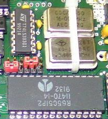
A bit like this:
click link for photo
The 74LS393 is near the silver can of the crystal module.
I used a 74LS393 because this circuit is not intended to operate at particularly high clock speeds. It having been built for experiments with NMOS and the older 2Mhz, 3MHz CMOS 6502 / 65C02 chips.
Mark
PS If I can find a higher resolution copy of this photo, I’ll post it up later.
Re: Clock generation for 6502
Posted: Wed Dec 18, 2019 4:30 pm
by ttlworks
Yes, something like this.
- drc2_clkgen.png (123.41 KiB) Viewed 3869 times
Unfortunately I don't have a bigger picture, and I don't have that hardware anymore.
The CPU was a Rockwell R65C02P2 (2MHz), but overclocking it to 4MHz had worked.
BDD, thanks for tossing in the electrical parameters of the WDC 65C02 clock input.
I never had used a WDC 65C02, nevertheless I _should_ have checked that datasheet before suggesting the 74393.
Re: Clock generation for 6502
Posted: Wed Dec 18, 2019 5:17 pm
by John West
I am experimenting a bit with direct crystal connection, but it does not work, could you please check my connection?
What is it doing, and what are you expecting it to do? "Doesn't work" can be anything from "it genuinely doesn't work" to "my expectations of what it should do were wrong".
Is that resistor connected to pin 40? It's hard to see where it goes. What value is it?
You haven't connected the data bus. With that floating, there's no telling what it'll try to do. Wire it to $EA for the classic NOP test.
Your LEDs are on the bottom two address lines. With a 2MHz clock, even with everything working you won't see anything. They'll both be on at 50% brightness. If you connect them to the top two address lines (pins 24 and 25), they'll be flashing at 15Hz and 30Hz - you might see a flicker on A15. That looks like a counter on the clock board. Divide it down by as much as you can. For the first steps, it's easiest to see what's going on if the clock is at a frequency that you can see an LED blinking.
If you have the tools to measure voltages, double-check that the power supply is providing 5V, and it's going to the right pins (and you've got it the right way around - 6502s don't like being fed -5V). If you have a logic probe or oscilloscope, check that there actually is a clock signal.
Put a capacitor across the power supply near the 6502. It might work without one, but breadboards and long wires make me nervous. 0.1uF is the traditional value. It wouldn't hurt to put something larger on it too.
And one last thing - is your larger breadboard one of the ones that split the power rails half way along? The wire you've got connected to pin 21 might not go anywhere.
Re: Clock generation for 6502
Posted: Wed Dec 18, 2019 5:43 pm
by BillO
I am experimenting a bit with direct crystal connection, but it does not work, could you please check my connection?
You might also want to tie pin 38 high too.