Page 1 of 2
Early pics of build
Posted: Fri Mar 17, 2017 4:07 am
by Dan Moos
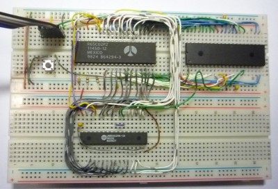
Data bus is finished. Totally happy with the decision to make custom ribbon cables. Not only is it clean, it completely eliminates any chance of getting lines crossed. I really want this thing to be ready to debug.
Re: Early pics of build
Posted: Fri Mar 17, 2017 9:28 am
by BigEd
I look forward to seeing what happens next. I am optimistic, but it's notable that this style of construction might be a worst-case for electric signal integrity. Please do proceed and try it - don't be put off - because we will all learn something here.
Re: Early pics of build
Posted: Fri Mar 17, 2017 1:12 pm
by Dan Moos
I'm only running the thing at 1 MHz.
Re: Early pics of build
Posted: Fri Mar 17, 2017 1:16 pm
by BigEd
That should certainly help. But, for example, if a clock signal is unclean, then frequency isn't the main concern - it's whether any receiver sees an edge which isn't there. I think if clocks and strobes (if any) are clean, and there's enough bypass caps near to the chips, there shouldn't be a problem. Synchronous design is a wonderfully forgiving world!
Re: Early pics of build
Posted: Fri Mar 17, 2017 6:45 pm
by GARTHWILSON
Keep in mind that it's not about the clock requency, but about the rise times and how the circuit reacts to them. In digital electronics, the rise time is independent of the frequency. In Jack Ganssle's YouTube video, "
I Only Probed the Board With a Scope - Why Did My Board Crash?," the part from about 2:20 to 3:00 graphically shows on an oscilloscope that the ugly ringing remains unaffected as he turns the clock frequency up and down. (This is in the "
Construction: Avoiding AC-Performance Problems" chapter in the 6502 primer.) The ringing will be worse, with greater amplitude, in a solderless breadboard, and can double-clock (or triple-clock, etc.) the processor, VIA, etc. with not enough time between pulses to react completely, and make it crash. Depending on the circuit, these unwanted pulses' apparent frequency may be 40MHz, 50MHz, or other frequency too high for these parts to work right. This is why the most important signal to keep clean is the Φ2 clock signal.
Re: Early pics of build
Posted: Fri Mar 17, 2017 8:52 pm
by BigDumbDinosaur
I'm only running the thing at 1 MHz.
Doesn't matter if the Ø2 clock signal when seen on a 'scope looks like the Chicago skyline.

This is why the most important signal to keep clean is the Φ2 clock signal.
Amen to that, which is why I go to considerable trouble to lay out the board so the Ø2 signal path is as short and direct as I can make it, especially if more than one device is using Ø2, e.g., a CPLD or a couple of VIAs.
Using a 74AC74 flip-flop to generate the actual Ø2 signal helps, as the flop's output is "stiffer" than that of a can oscillator (a 74AC74 can source or sink 24 mA), plus produces a symmetric output, which becomes important as the clock speed approaches the MPU's maximum rating. However, a stiff signal is not a substitute for a proper layout.
Everything going on in a 65xx system is ultimately slaved to the Ø2 clock. If you can't get Ø2 right your machine will be, at best, unstable.
Re: Early pics of build
Posted: Fri Mar 17, 2017 9:04 pm
by Dan Moos
I think I can get a pretty enough clock for this. I have with micro controller projects on similar bread boards. That is an analog problem, an area I have much more knowledge in than digital! My first move is to get the clock running and scope it. I'll send a pic of that when I do, with the relevant measurements on screen. You guys can tell me if I'm good I imagine.
Re: Early pics of build
Posted: Sat Mar 18, 2017 5:11 am
by BigDumbDinosaur
I think I can get a pretty enough clock for this. I have with micro controller projects on similar bread boards. That is an analog problem, an area I have much more knowledge in than digital! My first move is to get the clock running and scope it. I'll send a pic of that when I do, with the relevant measurements on screen. You guys can tell me if I'm good I imagine.
I saw the pic in another topic and commented.
Suggestion: instead starting multiple topics on your build keep on adding on to a single topic, thus making it a sort of build log. Doing so will make it a lot easier for other readers to follow along, and will create a "serial narrative" of your project from start to finish (not that any of these projects is really "finished"). My
POC V1 project is documented in a single topic that goes from when I was in the head-scratching phase to when I turned my attention to
POC V2. This approach will become valuable a few years down the road when someone is poking around here trying to find out what someone did to build their 6502 machine and they read what you have done.
Re: Early pics of build
Posted: Sat Mar 18, 2017 5:17 am
by Dan Moos
I can certainly do that. My next new topic will be suitably titled, and will be as you suggest.
I'm used to posting on the EEVblog forum, which is extremely busy, and thus fresh topics get seen. I'm starting to realize this is a much smaller group, so your idea would work fine here. Thanks as usual for the help!!
Re: Early pics of build
Posted: Sat Mar 18, 2017 5:56 am
by BigDumbDinosaur
I can certainly do that. My next new topic will be suitably titled, and will be as you suggest.
I'm used to posting on the EEVblog forum, which is extremely busy, and thus fresh topics get seen. I'm starting to realize this is a much smaller group, so your idea would work fine here. Thanks as usual for the help!!
Each time you add a post your topic will percolate up to the top of the new posts list. People will see it, as will anyone who uses the forum search functions to track down info about 65C02 builds.
Re: Early pics of build
Posted: Sat Mar 18, 2017 6:09 am
by GARTHWILSON
Also, if you keep adding new related material to your already existing topic, those who have already commented will get email notices, which won't happen if you start a new topic. Besides avoiding forum clutter, another benefit to keeping all the related material in the same topic is that if anyone needs to see the background, ie, how you got where you are, it's all there, and they don't have to go looking for another topic where you might have laid some background about what you're doing.
Re: Early pics of build
Posted: Sat Mar 18, 2017 6:23 am
by jac_goudsmit
When I started on my project over 6 years ago, I also put it together on a breadboard.
I also got this to run at 1MHz and didn't have any problems. That said, your mileage may vary!
By the way, I think you can get those rainbow ribbon cables at Adafruit, with ends connected for use on a breadboard...
Good luck on your project!
===Jac
Re: Early pics of build
Posted: Sat Mar 18, 2017 9:55 pm
by DerTrueForce
I can certainly confirm that your mileage may vary with a breadboard. I tried building up a basic system on a breadboard, and while I could get a NOP test to work, I never could get it working with ROM, RAM, and a VIA, because the connections got flaky. It works now, because I switched to a proto-board, but the wiring is butt-ugly under there. I can't really recommend that method of construction; it's nasty to try and refactor.
Re: Early pics of build
Posted: Mon Mar 20, 2017 7:53 pm
by Aslak3
I can certainly confirm that your mileage may vary with a breadboard. I tried building up a basic system on a breadboard, and while I could get a NOP test to work, I never could get it working with ROM, RAM, and a VIA, because the connections got flaky. It works now, because I switched to a proto-board, but the wiring is butt-ugly under there. I can't really recommend that method of construction; it's nasty to try and refactor.
Here's my breadboard micro, from a few years ago:
I would not call it bullet-proof, but it certainly ran for days on end without any issues, even with the horrible databus bridge between the boards. The clock was 2MHz (disclaimer: not a 6502, but with VIAs etc). Even the Compact Flash wedged into a IDC40 adapter was reliable.
So reliable breadboarding can certainly be achieved. For the epitomy of this, you only have to look at
Oneironaut's amazing work.
Re: Early pics of build
Posted: Mon Mar 20, 2017 10:37 pm
by Michael
The breadboard prototype of
My 3-Chip Design (Feb 2014) ran without problems at 1-MHz...