Page 1 of 2

Revolutionary no-solder wire-wrapping breakthrough!

Posted: Wed Feb 22, 2017 2:30 am
by cbmeeks
HA! Link-bait title. I know. LOL

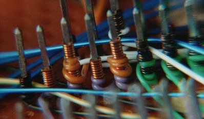
Anyway, I'm wire-wrapping a 65C02 computer and I'm trying NOT to solder anything. Mainly because I'm using the larger, more expensive breadboards and I make a lot of mistakes. :-D

So, I was thinking...how can I put passives on without soldering? Also, my wire-wrapping skills aren't good enough to wrap two poles 0.1" apart. So I had a brainstorm.

Why not put a 1x2 cutoff strip next to the power (for my bypass caps) and use a jumper on the bottom side! I have a crap ton of those jumpers and I think they may work pretty well for the few one-offs that I need right up next to the components.

Well, this was one of those moments where I thought to myself..."why didn't I do this before?" :-D

Oh, I'm sure I'm breaking every rule in the book but oh well. It's fun.

:-D

Re: Revolutionary no-solder wire-wrapping breakthrough!

Posted: Wed Feb 22, 2017 4:00 am
by GARTHWILSON
Answering Wire-Wrap (WW) Questions and Doubts: http://wilsonminesco.com/6502primer/WireWrap.html

The pin's clean, sharp corners should bit into the wire four times in every turn, not having the bare wire go outside of previous turns. If you keep to this, you won't have any trouble wrapping wires .1" apart and running more wires in between on their way by, and you'll have a 100.00% reliable connection, for as many decades as you want to use it, without soldering.

Image

The black ones here are silver-plated wire that's tarnished unevenly, but the wraps are even. The smoothness is more visible in the copper wires. The neatness is for reliability, not looks.

Re: Revolutionary no-solder wire-wrapping breakthrough!

Posted: Wed Feb 22, 2017 12:10 pm
by cbmeeks
Right, that's the tutorial I've followed many many times.

My issue is two things. 1) I have trouble stripping the wire when I'm really close to a pin. 2) My eyesight. It's very hard for me to see those pins many times so I'm usually wire-wrapping by feel. I don't seem to have this problem with soldering for some reason. But then again, I use a magnifying glass with that.

I've tried the magnifying glass with wire-wrapping but it doesn't work as well for me. I sometimes have a hard time seeing the pins against the background of the vias and other pins. Almost like a "snow blindness" effect. Like I said, my vision isn't the best. :-)

Re: Revolutionary no-solder wire-wrapping breakthrough!

Posted: Wed Feb 22, 2017 4:10 pm
by KC9UDX
Have you thought about a camera and a monitor? Cameras are dirt cheap these days. You have better control over lighting and zoom with a camera than a magnifier. Plus, with the size of cameras now, you can position them in ways that aren't practical with a magnifier.

Re: Revolutionary no-solder wire-wrapping breakthrough!

Posted: Wed Feb 22, 2017 4:51 pm
by cbmeeks
KC9UDX wrote:
Have you thought about a camera and a monitor? Cameras are dirt cheap these days. You have better control over lighting and zoom with a camera than a magnifier. Plus, with the size of cameras now, you can position them in ways that aren't practical with a magnifier.
Actually, I have. It's on my wish-list of toys to buy. I have plenty of monitors. I sometimes buy them from Goodwill for next to nothing.

Do you have a particular model to recommend?

Re: Revolutionary no-solder wire-wrapping breakthrough!

Posted: Wed Feb 22, 2017 10:27 pm
by KC9UDX
Unfortunately I do not. I've only talked to other guys using them, and never asked for details.

Re: Revolutionary no-solder wire-wrapping breakthrough!

Posted: Wed Feb 22, 2017 11:37 pm
by unclouded
cbmeeks wrote:
Do you have a particular model to recommend?
I have one of these, which I like:

http://www.ebay.com/itm/Supereyes-200X- ... 1235531525

It's good for inspecting soldering on PCBs too (I mount it in a 3-axis machine for this). It's UVC, so works on Linux.

Re: Revolutionary no-solder wire-wrapping breakthrough!

Posted: Fri Feb 24, 2017 9:09 pm
by EugeneNine

Re: Revolutionary no-solder wire-wrapping breakthrough!

Posted: Sat Feb 25, 2017 4:33 am
by KC9UDX
EugeneNine wrote:
250x is far too strong. Chances are pretty good it can't zoom out far enough to be useful.

Also, that arm may not give you enough working space.

Re: Revolutionary no-solder wire-wrapping breakthrough!

Posted: Sat Feb 25, 2017 7:12 pm
by EugeneNine
Its up to 250x. I was looking for something with a stand,I have a small pen like one like in the ebay link but wanted something I don't have to hold (and don't want to have to buy from ebay).

Re: Revolutionary no-solder wire-wrapping breakthrough!

Posted: Wed Mar 01, 2017 11:24 pm
by GaBuZoMeu
KC9UDX wrote:
Have you thought about a camera and a monitor? Cameras are dirt cheap these days. You have better control over lighting and zoom with a camera than a magnifier. Plus, with the size of cameras now, you can position them in ways that aren't practical with a magnifier.
I have once done this - repairing 0.5 mm fine pitch SMD parts - some years ago. It works but there are some issues you should consider:

1. The display (usally a monitor) is placed in a different location than your hands are working - it´s unpleasant to look ahead or aside AND working in front. It takes some time to become 'familiar' with that. I remember I feeled pretty much exhausted after doing that 1/2 hour or so.

2. Simple cameras/USB microscopes have automatic brightness control. If you can´t turn that off your picture (especially in higher magnification) is frequently changinbg the avarage brightness when you move the iron tip, when the shiny solder wire appears, and the solder smoke comes up. This can be annoying as well.

3. the frame rate should be at least 50/s otherwise there is a noticeable lag.

4. Lighting can be very difficult.

5. Having only one camera means working monoccular - it is a bit difficult to figure out the z-distance. And moving your head doesn´t change the view :P

Today I have access to a large stereo-microscope (just optics, no electronics). This is very pleasant.


Arne

Re: Revolutionary no-solder wire-wrapping breakthrough!

Posted: Thu Mar 09, 2017 8:24 am
by Bregalad
Wire-wrapping is nothing new or revolutionary and had been there for decades. It's great but the main 2 problems are that 1) you need sockets for everything, and adapters so that everything is in DIP format and 2) it's extremely though to debug.

However you still need to solder at least 2 pins on each socket so that they hold mechanically, don't you ? You could also make them hold in place using a different strategy such as paste, though.

Re: Revolutionary no-solder wire-wrapping breakthrough!

Posted: Thu Mar 09, 2017 9:37 am
by GARTHWILSON
Bregalad wrote:
It's great but the main 2 problems are that 1) you need sockets for everything,
and they've become pretty expensive!
Quote:
and adapters so that everything is in DIP format
There are PLCC WW sockets too but they're rare and super expensive, $10 to $20 each! Things like resistors, capacitors, and crystals can go on individual WW pins that are not part of a socket. The pin gets pressed into the board, you solder the component to it on the top of the board, and wire-wrap the pin underneath. If you have several in the same area, you can put them on DIP headers and plug them into WW DIP sockets, but I'm finding the DIP headers are becoming rare too, at least in the bigger sizes (like 20, 24, 28, 32, and 40 pins).
Quote:
and 2) it's extremely though to debug.
That's probably more true if you make wire lengths longer than they need to be to make the connection in a rather straight line. Making the connections direct and short improves performance and facilitates debugging. I've had virtually no debugging to do after the build though. I do make mistakes, but I catch them long before I'm done, like noticing that there are already two wraps on a post that should only have one (where did the other one come from?) or that something that I thought I had a previous connection on does not (where did the errant wire go?), or that I ran out of pins in a row before I ran out of things that were supposed to go there, etc.. When I find a wire went to the wrong post, it's always still on top, so I don't have to unwrap something above it to get to it.
Quote:
However you still need to solder at least 2 pins on each socket so that they hold mechanically, don't you ? You could also make them hold in place using a different strategy such as paste, though.
It's good, but not essential, to have the sockets mechanically pre-held to the board. I've wire-wrapped circuits where the only thing holding the sockets to the board is the wraps themselves, and never had a problem.

Re: Revolutionary no-solder wire-wrapping breakthrough!

Posted: Thu Mar 09, 2017 8:17 pm
by cbmeeks
Bregalad wrote:
Wire-wrapping is nothing new or revolutionary and had been there for decades.
Yeah, I was sort of making a joke. Sarcasm. :-)

Bregalad wrote:
It's great but the main 2 problems are that 1) you need sockets for everything,
Sockets are needed and like stated before, they can be very expensive. Especially PLCC sockets.
Bregalad wrote:
2) it's extremely though to debug.
I don't see how it could be any more difficult than point-to-point soldering. Whenever I finish a run of wire, I always test it with my multimeter. Plus, I check the entire bus frequently as I go along to make sure I didn't break something.
Bregalad wrote:
However you still need to solder at least 2 pins on each socket so that they hold mechanically, don't you ?
I started a wire-wrapped computer a while back and I did that. I soldered a pin on each wire-wrap socket. I *really* wished I hadn't done that. I've started another wire-wrapped computer and so far I haven't soldered any sockets at all. I find the wire-wrapping is so strong, that the socket actually feels soldered on. Think about it, you typically have 16, 24, 28, 40, etc. pins each with a solid connection. The first wire I put on the pin, I try to make sure it's flush with the board. That keeps it from flopping around.

Now, going back to my first wire-wrapped computer...the one with the soldered pins. I've been trying to take it apart for hours. I've cut wires, "un-wrapped" them with my wire-wrapping tool, etc. It's incredible how secure those wires are.

When trying to de-solder the pins, I've managed to break a couple of them. Which REALLY sucks since some of these sockets are $5 each.

Fortunately, you can buy a row of pins from Jameco for a few dollars. I can then pull the pin out of those and repair the more expensive sockets.

So, in my new wire-wrapped computer, I haven't soldered anything *except* for a few sockets. But NONE OF THE SOCKETS are soldered to the board.

What I did was take some 8 pin wire-wrap sockets and soldered 3.3k resistors on the pins. I then wire-wrap this socket and use it for pull-up lines. I've done the same thing with capacitors.

I find that works pretty well. And, the great thing is that I can reclaim the sockets even easier the next time because none of them are soldered to the board.

Bregalad wrote:
You could also make them hold in place using a different strategy such as paste, though.
No need.

If my computer were going to be moved around a lot, in an environment with lots of vibration, then I might do something different. But like I said, once the sockets are wire-wrapped, they're not going anywhere.

Re: Revolutionary no-solder wire-wrapping breakthrough!

Posted: Thu Mar 09, 2017 9:10 pm
by GARTHWILSON
If you do solder WW pins, use as little solder as you can get away with for the job, and be sure the solder doesn't run up the pin to an area you want to wrap in the future. You want the corners of the pins to be really sharp so they'll bite into the wire, and totally flux-free so there's no barrier to a good chemical weld.