6502.org Forum  Projects  Code  Documents  Tools  Forum
It is currently Sat Apr 20, 2024 12:40 pm

All times are UTC


Post new topic Reply to topic  [ 65 posts ]  Go to page 1, 2, 3, 4, 5  Next
Author Message
 Post subject: MOS 6509 look-alikes?
PostPosted: Thu Dec 22, 2011 2:43 pm 
Offline

Joined: Tue Sep 24, 2002 4:56 pm
Posts: 50
Location: Essex, UK
Out of curiosity (and with all the recent topics on tracking and replacing or enhancing 65xx opcodes), has anyone tried adding external logic to a (modern/WDC) 65C02 to turn it into something that looks and acts like a MOS 6509?

--Martin

For those who are unsure, the MOS 6509 has a pair of 4-bit memory-mapped registers - at $0000/$0001 - that extend the addressing range of the CPU to 20 bits, or 1MB; one is the "code" register, that is used on most memory accesses, and the other is the "data" register, used on the (the "significant" load/store operation of the) "LDA/STA (zp),Y" instructions (opcodes $B1/$91).

_________________
Martin Penny

.sig in beta - full release to follow.


Top
 Profile  
Reply with quote  
PostPosted: Thu Dec 22, 2011 7:03 pm 
Offline

Joined: Sun Sep 15, 2002 10:42 pm
Posts: 214
mdpenny wrote:
Out of curiosity (and with all the recent topics on tracking and replacing or enhancing 65xx opcodes), has anyone tried adding external logic to a (modern/WDC) 65C02 to turn it into something that looks and acts like a MOS 6509?

--Martin

For those who are unsure, the MOS 6509 has a pair of 4-bit memory-mapped registers - at $0000/$0001 - that extend the addressing range of the CPU to 20 bits, or 1MB; one is the "code" register, that is used on most memory accesses, and the other is the "data" register, used on the (the "significant" load/store operation of the) "LDA/STA (zp),Y" instructions (opcodes $B1/$91).


Unless you need compatibility with the 6509, you're probably better off using a 65816.

It has address space extended in a kludgy way, but it's better than this method.

Toshi


Top
 Profile  
Reply with quote  
 Post subject:
PostPosted: Sun Dec 25, 2011 7:15 am 
Offline
User avatar

Joined: Fri Dec 11, 2009 3:50 pm
Posts: 3343
Location: Ontario, Canada
I agree with Toshi that, as an off-the-shelf solution, the '816 is preferable to a MOS 6509. But, Martin, you sound as if you're motivated by curiosity, and perhaps aren't concerned so much about the practicalities of actually building a system.
Quote:
has anyone tried adding external logic to a (modern/WDC) 65C02 to turn it into something that looks and acts like a MOS 6509?

"Like" a MOS 6509, or identical? I haven't heard of anything that exactly duplicates the 6509 approach to expanded address space. But what's distinctive about the 6509 (and 65816) approach is that it expands the address space in bankwise fashion, 64K at a time, as opposed to forcing the programmer to funnel everything through (say) 8K or 16K chunks.

Back in the 20th century I developed two homebrew projects which use the banked address approach (neither of them influenced by the '816 or 6509). My KimKlone computer is a microcoded design that offers a lot of extra bells and whistles beyond just extra memory addressing. In case you missed it, the machine is documented here, and there's a 6502.org thread here.

But the preceding design is much simpler, and maybe closer to the intended topic. The project was a mod to my KIM-1. In essence there wasn't much to it beyond the previously discussed Ultra-fast output port using 65C02 illegal instructions. In this case the output port fed some logic that loaded a shift register whose delayed serial output controlled A16, the 17th address line in my 128K KIM-1 (!) :shock:

Each access to extended memory required two instructions -- together the pair functioned as one. The program would use an illegal instruction to load the shift register, and the following instruction would be the actual memory reference -- LDA, ADC, STA or whatever. On the bus cycle when the LDA (or whatever) did its data access, that's when the shift register would -- for one cycle only -- switch to the alternate bank. Of course the timing had to be perfect. It was imperative for the programmer to look at the instruction and its address mode to determine in advance the number of bus cycles of delay until the bus cycle for data access would occur. Without this information it'd be impossible to select the illegal op that generates the correct timing. :roll: The project worked, but it was a long way from being programmer friendly!


Speaking of unfriendly, the MOS 6509 datasheet seems rather opaque, with quite a lot left unsaid. And, absurdly enough, it shows a 64K memory map rather than the entire 1MB! Can we conclude that the pair of 4-bit memory-mapped registers appear only in Bank 0? Or are they at the bottom of every bank?

Cheers,

Jeff


Top
 Profile  
Reply with quote  
 Post subject:
PostPosted: Sun Dec 25, 2011 11:13 am 
Offline

Joined: Tue Sep 24, 2002 4:56 pm
Posts: 50
Location: Essex, UK
Dr Jefyll wrote:
I agree with Toshi that, as an off-the-shelf solution, the '816 is preferable to a MOS 6509. But, Martin, you sound as if you're motivated by curiosity, and perhaps aren't concerned so much about the practicalities of actually building a system.

Quote:
has anyone tried adding external logic to a (modern/WDC) 65C02 to turn it into something that looks and acts like a MOS 6509?


"Like" a MOS 6509, or identical? I haven't heard of anything that exactly duplicates the 6509 approach to expanded address space. But what's distinctive about the 6509 (and 65816) approach is that it expands the address space in bankwise fashion, 64K at a time, as opposed to forcing the programmer to funnel everything through (say) 8K or 16K chunks.


I was indeed asking out of curiosity (EDIT: a "thought experiment", of sorts) - and (from my limited experience of *building* such things) I suspect it probably wouldn't be overly "difficult" to do, perhaps even in discrete logic (do-able if the CPU's being clocked at the same 1 to 2 MHz that the 6509 originally was).

Dr Jefyll wrote:
Speaking of unfriendly, the MOS 6509 datasheet seems rather opaque, with quite a lot left unsaid. And, absurdly enough, it shows a 64K memory map rather than the entire 1MB! Can we conclude that the pair of 4-bit memory-mapped registers appear only in Bank 0? Or are they at the bottom of every bank?


My guess? The registers would appear at these addresses on all "code" bank accesses, but *not* on the "data" bank accesses.

From reading between the lines of some details of the CBM-II range of machines, the designers put the boot ROMs and I/O in bank #15 (the default at power-up), with bank #0 being video memory, and banks #1 and #2 (on 128KB machines) or #1 to #4 (on 256KB machines) for data - the CBM BASIC 4.0 (two versions, one for each memory layout) then split the BASIC program and data across these banks. I suspect they indended code to run only ever from bank #15 - this meant that the "code" register would not need to be changed, and the "inter-bank" code calls would be avoided (it looks like they'd be a PITA).

--Martin

(PS: Is Steve Gray, the maintainer of the above CBM-II pages, reading this forum? If so, I may have some extra "stuff" for your pages.)

_________________
Martin Penny

.sig in beta - full release to follow.


Top
 Profile  
Reply with quote  
 Post subject:
PostPosted: Mon Dec 26, 2011 5:30 pm 
Offline

Joined: Sat Aug 15, 2009 8:08 pm
Posts: 29
The two CPU registers at $00 and $01 appear in all banks.

Yes, all ROMS and I/O appear in BANK 15. In the B-Series only the dedicated BANK 15 video ram can be accessed by the CRTC chip. In the P-series (P500) the VIC-II can also access BANK 0. In the B-series there is no ram in BANK 0. In both machines only BANK 1 can be used for BASIC code. In the 128K machines BANK 2 is for all BASIC variables, whereas in the 256K machines the variables are distributed by type to BANKS 2, 3 and 4.

Code can run in any bank. There is a great article in transactor magazine, written by Jim Butterfield about all the hoops you have to go through to execute code in any non-bank15 ram.

Martin, I'd definately be interested in anything you have that I can add to my page.

Steve


Top
 Profile  
Reply with quote  
 Post subject:
PostPosted: Mon Dec 26, 2011 5:49 pm 
Offline

Joined: Tue Sep 24, 2002 4:56 pm
Posts: 50
Location: Essex, UK
Thanks for the correction - I had (clearly) jumped to the wrong conlusion about what was where.

The "stuff" I have is a review from the "Personal Computer News" magazine (of the early 80's) of (some of) the CBM-II computers; I shall dig it (and a scanner) out and PM you with the file sizes &c before posting it to you.

--Martin

_________________
Martin Penny

.sig in beta - full release to follow.


Top
 Profile  
Reply with quote  
 Post subject:
PostPosted: Tue Dec 27, 2011 4:49 am 
Offline
User avatar

Joined: Fri Dec 11, 2009 3:50 pm
Posts: 3343
Location: Ontario, Canada
sjgray wrote:
The two CPU registers at $00 and $01 appear in all banks.

Thanks, Steve. Let me double-check that I understand. You are saying that the memory-mapped registers appear
  • anytime A15-A0 equal $0000 or $0001
  • the four-bit bank-select address is irrelevant, and
  • it is irrelevant whether the $0000 or $0001 on A15-A0 was generated by (Ind),Y address mode or by some other address mode
If you can confirm this or else offer clarification I'd appreciate it. Also, what about Zero Page and the Stack? Do they change banks when the Code Bank changes, or does the 6509 always divert Z-Pg and Stack references to Bank 0?

cheers,

Jeff


Top
 Profile  
Reply with quote  
 Post subject:
PostPosted: Tue Dec 27, 2011 11:38 am 
Offline
User avatar

Joined: Thu Dec 11, 2008 1:28 pm
Posts: 10791
Location: England
Interesting stuff! I find two likely-looking articles in transactor by Jim Butterfield:
The C128 - You can bank on it July 86, Vol7, issue 1, p34 (pdf) also here on scribd
The Commodore 128 - Banking on the Turns Jan 87, vol 7, Issue 4 (pdf) also here on scribd
(Edit: wrong articles, wrong machine - see downthread.)

My guess would be that the on-chip registers would appear in all banks and both 'modes'. Note that the banks as known to the OS on the C128 are mapped by the MMU, so they are complex memory maps which do seem to carry the zero page and stack with them into every bank, as well as the MMU itself. The CPU only knows about the four extra pins P0..P3.

I agree with Jeff, that Toshi is right to suggest the '816 for a quick self-contained way to exceed the 64k limit, but for an interesting project making a 6509 workalike is promising. There's no need to limit to 4 bits of bank address either. You do need to count from the SYNC to the final cycle of the two affected opcodes though, discounting RDY stalls, so it isn't trivial.

What I like about the 6509 approach is that it's minimal. It doesn't introduce 3-byte pointers and it could leave most existing code unchanged running in a single 64k bank. Only long-distance data accesses need be affected, which is ideal for an interpreted language or for data storage/retrieval (like photoframes.)

(Let's not forget Acorn's in-house Turbo machine, which did use 3-byte pointers, placing the high byte in page 03. This was built using discrete components around an existing CPU, so could be done again.)

Cheers
Ed


Last edited by BigEd on Sat Nov 04, 2017 4:48 pm, edited 1 time in total.

Top
 Profile  
Reply with quote  
 Post subject:
PostPosted: Tue Dec 27, 2011 12:12 pm 
Offline

Joined: Tue Sep 24, 2002 4:56 pm
Posts: 50
Location: Essex, UK
(Yup, the '816 looks more straightforward, and also easier, to design around so it can be run at up to its max. clock speed; "hacking" an '02 with external logic would likely impose limits on performance.)

And another possible solution might be to use one of the FPGA-type 6502 cores, adding the extra logic in at that stage; this way, it should be easier to "tap into" the internal control signals, making the decoding more straightforward.

(FPGA'ing a CBM-II might be an idea for a project, especially as similar projects are underway for the PET and BBC Micro.)

--Martin

_________________
Martin Penny

.sig in beta - full release to follow.


Top
 Profile  
Reply with quote  
 Post subject:
PostPosted: Tue Dec 27, 2011 8:24 pm 
Offline

Joined: Sat Aug 15, 2009 8:08 pm
Posts: 29
Dr Jefyll wrote:
sjgray wrote:
The two CPU registers at $00 and $01 appear in all banks.

Thanks, Steve. Let me double-check that I understand. You are saying that the memory-mapped registers appear
  • anytime A15-A0 equal $0000 or $0001
  • the four-bit bank-select address is irrelevant, and
  • it is irrelevant whether the $0000 or $0001 on A15-A0 was generated by (Ind),Y address mode or by some other address mode
If you can confirm this or else offer clarification I'd appreciate it. Also, what about Zero Page and the Stack? Do they change banks when the Code Bank changes, or does the 6509 always divert Z-Pg and Stack references to Bank 0?

cheers,

Jeff


This is from memory, so hopefully I remember...

There is no separate MMU chip in the CBM-II machines. All this is handled in the 6509 CPU. Any write, no matter how to $00 and $01 affect the CPU registers, from any write instruction, from any bank. These registers are 4 bits each for 16 banks or 1MB address space. Think of the 16 banks of 64K stacked on top of each other. On reset both $00 and $01 are set to $FF (well, $0F since there are only 4 bits). Register $00 is the "execution" register. This is the bank that is running the code. Any write to $00 immediately changes the BANK, but not the address counter, so code execution just keeps going but in a different bank, which means code must be syncronized. The $01 register is the "indirect" register, which determines which bank is used for memory reads and writes using the 'indirect indexed' instructions. Each bank (with memory in it) has it's own zero page and stack. There are special "transfer" routines in the kernal for calling BANK 15 Kernal routines from another bank.

Jim B's article "B500 Machine Language Transfer Sequences" can be found in Transactor, July 1983. If requested I can make this available on my CBM-II page.

Steve

Disclaimer: I haven't programmed in 6509 code for many years.

PS: Count me in for a CBM-II emulator in FPGA!!!! ;-)


Top
 Profile  
Reply with quote  
 Post subject:
PostPosted: Tue Dec 27, 2011 8:49 pm 
Offline
User avatar

Joined: Thu Dec 11, 2008 1:28 pm
Posts: 10791
Location: England
Ah, thanks for the correction (I had the wrong machine and so found the wrong articles)

The right article then is on page 60 of the pdf found here.

Cheers
Ed


Last edited by BigEd on Thu May 19, 2022 9:10 am, edited 1 time in total.

Top
 Profile  
Reply with quote  
 Post subject:
PostPosted: Fri Dec 30, 2011 7:24 am 
Offline
User avatar

Joined: Fri Dec 11, 2009 3:50 pm
Posts: 3343
Location: Ontario, Canada
sjgray wrote:
Each bank [...] has it's own zero page and stack.

Thanks, Steve. I think this reveals the 6509 is not a specially designed CPU -- instead it's just a sidecar hung on the 6502 (sort of like the 2A03, which uses a stock 6502 mask but with a bit of extra logic added around the perimeter). 
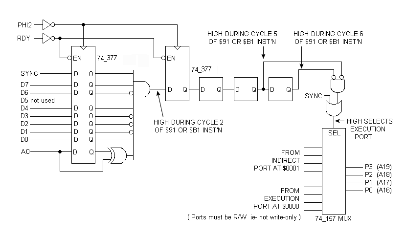
Here is my version of add-on logic for a 6509 look-alike. If my understanding of the 6509 is correct, then this circuit, connected to a 6502, should reproduce 6509 behavior. [Edit: confirmed -- see subsequent posts.]

Attachment:
6509_look-alike.png
6509_look-alike.png [ 11.21 KiB | Viewed 6515 times ]


I drew this with 6502 in mind but offhand see no reason it wouldn't be OK for the 'C02 or even the '816. The circuit detects the opcode fetch of the two modified 6509 instructions, STA (Ind),Y and LDA (Ind),Y (op-codes $91 and $B1). The data access occurs later -- either during in cycle 5 or 6. It'll be cycle 5 only if the access is a read and no page crossing occurs, as per normal 6502 behavior. During cycle 5 (and cycle 6, if it's present) the Indirect memory bank is selected by the 74_157 mux. If it's a read with no page crossing, cycle 6 will be absent, as per normal 6502 behavior. In that case the circuit uses SYNC to ensure it'll be the Execution bank that's selected for the opcode fetch in the cycle which follows cycle 5.
Note:
  • I haven't bothered to draw the output port logic that provides the two bank addresses.
  • the '377 is an octal, edge-triggered register similar to '374 or '574, but clocking with /EN high ignores the new input data on D and reloads the data already on Q. IE: the output remains unchanged.
  • The XOR gate protects against the false opcode fetch that occurs whenever an interrupt is recognized. There's a risk that a $91 or $B1 opcode will get fetched but not executed. If this happens the circuit mustn't respond. To recognize the beginning of the cpu's interrupt sequence we look for the unique circumstance of the address bus failing to increment in the cycle following an opcode fetch. No increment means the least-significant address line, A0, will fail to toggle. The output of the XOR gate will be low, thus inhibiting the circuit.
  • To simplify the circuit D1 could be ignored (like D5). This would render the circuit susceptible to triggering from opcodes $93 and $B3, but these are undefined op's anyway.

mdpenny wrote:
"hacking" an '02 with external logic would likely impose limits on performance

Right, Martin -- certainly that's a legitimate concern for this circuit (in its present form). For example in some situations there'll be no valid bank address until SYNC has had time to propagate into the mux. At NMOS CPU speeds that's a fairly trivial delay, but for a modern 'C02 running at, say, 14 MHz, it's much more of an issue. Hmmm.... For the '816 you could make use of VPA and VDA signals, which would inform you in cycle 5 whether there's a page crossing. Having that advance notice means you could use fully synchronous logic and eliminate the performance limit. IOW you could 6509-ify an '816 and run it at the full 14 Mhz.

The FPGA approach is attractive too, of course. (I mean with the cpu core implemented on FPGA.) The add-on approach could be abandoned for something more elegant and resource-efficient!

Since the goal seems to be to run pre-existing CBM-II code, the question arises whether the FPGA core would have to accurately reproduce undefined 6502 op's. Do CBM-II applications use illegal instructions?! (This issue would also affect the 'C02 and '816 add-on look-alikes.)

-- Jeff

Edits: Fix typo. Improve clarity. Fix booboo: '377 register, not '273.
Edit (2018): Improve clarity. Fix booboo: the Enable on a '377 is active low, not active high. The updated diagram reflects this. Also, the original logic (shown below) unnecessarily imposed two gate delays between SYNC and the mux.
Attachment:
previous version of logic.png
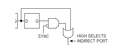
previous version of logic.png [ 1.93 KiB | Viewed 6515 times ]


Last edited by Dr Jefyll on Fri Dec 28, 2018 2:33 am, edited 5 times in total.

Top
 Profile  
Reply with quote  
 Post subject:
PostPosted: Fri Dec 30, 2011 9:51 am 
Offline
User avatar

Joined: Thu Dec 11, 2008 1:28 pm
Posts: 10791
Location: England
Excellent! About the speed concern: wrapping all this glue, including the two ports, into a CPLD, is a possible answer. I haven't counted up the required pins though. An off the shelf CPU plus a CPLD is a useful step, short of going for a custom CPU on an FPGA. And for this level of complexity it's natural to design with schematics, so no particular need to learn an HDL.

That said, the same design could readily be combined with an existing 6502 core in an FPGA.

Cheers
Ed


Top
 Profile  
Reply with quote  
 Post subject:
PostPosted: Fri Dec 30, 2011 10:49 am 
Offline

Joined: Tue Jul 05, 2005 7:08 pm
Posts: 990
Location: near Heidelberg, Germany
Excellent work indeed!

Dr Jefyll wrote:
Note:
  • ...
  • The XOR gate protects against the false opcode fetch that occurs whenever an interrupt is recognized. There's a risk that a $91 or $B1 opcode will get fetched but not executed. If this happens the circuit mustn't respond. To recognize the beginning of the cpu's interrupt sequence we look for the unique circumstance of the address bus failing to increment in the cycle following an opcode fetch. No increment means the least-significant address line, A0, will fail to toggle. The output of the XOR gate will be low, thus inhibiting the circuit.
  • ...


That was my initial concern but you have handled that as well! Great work! Only one question: Have you run that through visual 6502 that there is a cycle where PC is not incremented before the IRQ handling starts? Otherwise assume the opcode is on an odd address, the IRQ kicks in, and then what happens in the two "internal operations" cycle, maybe it does actually increase PC? I couldn't find this on a quick search...

André


Top
 Profile  
Reply with quote  
 Post subject:
PostPosted: Fri Dec 30, 2011 3:24 pm 
Offline
User avatar

Joined: Fri Dec 11, 2009 3:50 pm
Posts: 3343
Location: Ontario, Canada
Right, then! If that goofy kludge makes sense to you guys then I know I'm not completely crazy! (Or, if I am, at least I have some company.)

BigEd wrote:
There's no need to limit to 4 bits of bank address either
Quite right. Our add-on logic needn't be limited to 1 MB (4 extra address bits). We can easily go as high as 16MB (8 extra bits) -- or even higher if we find a way to map in wider ports.

Actually I'm disappointed to learn that the 6509 is so primitive. On the one hand it is better than conventional mapping schemes that deal in, say, 8K or 16K chunks. (These clever but constricting schemes seem to be by far the most widely adopted means of beating the 64K barrier.)

On the other hand, the 6509 falls short of what it could have been. Because it maps the ports to $0000 and $0001 of every bank, the 6509 is incapable of hosting an array or other object greater than 64K-2 in size. IMO this limits you to small-computer goals, in contrast to the '816 and and my Kimklone which let you accommodate and linearly address any object that'll fit in memory.

fachat wrote:
I couldn't find this on a quick search...

The lack of PC incrementing during interrupt recognition is documented on page A-11, Table A. 5.4 of the MOS Hardware Manual and in Table 5-7 of the '816 Data Sheet. There's an old and somewhat fragmented 6502.org discussion of the topic here. See also the visual6502.org/wiki/ page here.

cheers,

Jeff
[edited to include Ed's comment and the link to the visual6502.org wiki page]


Top
 Profile  
Reply with quote  
Display posts from previous:  Sort by  
Post new topic Reply to topic  [ 65 posts ]  Go to page 1, 2, 3, 4, 5  Next

All times are UTC


Who is online

Users browsing this forum: No registered users and 1 guest


You cannot post new topics in this forum
You cannot reply to topics in this forum
You cannot edit your posts in this forum
You cannot delete your posts in this forum
You cannot post attachments in this forum

Search for:
Jump to: