6502.org Forum  Projects  Code  Documents  Tools  Forum
It is currently Tue Mar 19, 2024 9:56 am

All times are UTC


Post new topic Reply to topic  [ 49 posts ]  Go to page 1, 2, 3, 4  Next
Author Message
PostPosted: Fri Sep 03, 2010 1:55 pm 
Offline

Joined: Thu Sep 02, 2010 12:34 am
Posts: 36
Location: Salzburg, Austria
I recently ran into a very strange thing on my Atari 800XL I never heard or read about before:

If a 3-cycle branch instruction (i.e. a taken branch not crossing a page boundary) ends in the cycle before the 6502 would normally start the 7-cycle interrupt execution, the 6502 executes another full instruction and starts with interrupt handling after that. I tested this both with IRQs and NMIs, and the results were identical.

With all other instructions I tested so far, including 2-cycle branches (i.e. branch not taken) and 4-cycle branches (i.e. branch taken crossing a page boundary) the behaviour is as expected: the instruction finishes and the CPU starts with interrupt handling immediately in the next cycle.

The Atari XL and XE series use an extended NMOS 6502 CPU, but AFAIK the only changes to the original NMOS 6502 was the addition of some halt logic and bus isolation circuits.

AtariAge user bob1200xl also verified this on an Atari 800, which uses a standard 6502 and has the bus-isolation built with discrete logic. So I assume that other NMOS 6502 might also be affected by this "bug". A test on a 65816 didn't show this behaviour, so I guess the CMOS variants could have been fixed.

My question now is: has anyone experienced such behaviour before and maybe knows what's going on inside the NMOS 6502?

We are currently discussing this issue over on the AtariAge forum in this thread but are kind of clueless. We suspected that there might be going on something strange at the transition of T2 of the branch instruction to T0 that might block interrupt execution in T0. But this is just a wild guess.

Now for some more background information:

I wrote a simple test program for my Atari which basically just aligns some code so that the last cycle of an instruction executes just before the interrupt fires. This code is followed by some dummy instructions (I used "LDA #1", "LDA #2", "LDA #3"). The interrupt handler then just reads the return-address from the stack and stores it, and by looking at the code at this address (either pointing to "LDA #1" or "LDA #2") I know where the interrupt occured.

The test code looks like this (interrupt setup and most of the code alignment has been done before):
Code:
        SEC
        LDX ZPTEMP
        LDX ZPTEMP
        BCS CBCST1
CBCST1
; <-- interrupt should occur here
        LDA #1
; <-- but actually is executed here
        LDA #2
        LDA #3

Note: I just used the "BCS 0" for simplicity, in a "real world" code I had a BNE branching several cycles away. The behaviour showed up in all cases.

An now the interrupt handler:
Code:
; IRQ code: store the return address
MYIRQ   PHA
        TXA
        PHA
        TSX
        LDA $0104,X
        STA RETADR
        LDA $0105,X
        STA RETADR+1
        LDA #0
        STA IRQEN
        PLA
        TAX
        PLA
        RTI


You can download my test code (including source, binaries for the Ataris and logic analyzer captures) from my homepage.

First version, using the vertical blank NMI: http://www.horus.com/~hias/tmp/vbitest-1.0.zip
Second version, testing with vertical blank NMI and pokey timer IRQ, also test for 4-cycle branch crossing page included:
http://www.horus.com/~hias/tmp/inttest-1.0.zip

Another note: on the Atari the Pokey IRQ timing is quite tight, Pokey asserts the IRQ quite late during phase 2, so on some computers the IRQ setup time for this cycle is not met and everything is delayed by 1 cycle (so the 6502 executes the next instruction in all cases, as it only "saw" the interrupt being asserted for one cycle). On the Ataris the NMI timing is a lot more reliable as the Antic asserts NMI early during phase 1. You might need to take care of similar effects when you try to repoduce it on other systems.

I hooked up my logic analyzer to check what was going on. First a screenshot of the expected behaviour (using a 2-cycle not-taken branch):
Image
At ~81us the CPU fetches the BCS opcode and NMI goes low. At the end of this cycle the CPU recorded the first-low-cycle of NMI. In the next cycle the CPU fetches the offset, NMI is still low and the CPU records the second-low-cycle so interrupt execution can start. Then, in the next cycle, the 7-cycle interrupt execution starts.

Now the screenshot of the 3-cycle branch leading to the execution of another instruction:
Image
At ~81us CPU fetches BCS opcode, in the next cycle the offset, also NMI goes low, then the CPU executes the branch, and now the NMI should be serviced. But the CPU fetches the next opcode ("A9" / "LDA #"), and the data ("01"), and after that starts with the 7-cycle interrupt sequence.

Here's another screenshot from my real-world code (sampled at Atari clock speed at the falling edge of PHI2 - ignore the timestamps at the top, they are a dummy 1us per sample). First there's a BNE backwards, followed by a "BIT $D20E" executed instead of the NMI handler:
Image

I did some research, but the only thing I found was a little thing in the MOS hardware manual: On page A-13 in the description of the branch instruction the (dummy) opcode fetches in states T2 and T3 didn't have word "discarded" with them (as the other dummy reads have), and the T0 cycle afterwards wasn't mentioned. But this could also be some simple typos and don't have to mean anything.

I would be quite interested if someone could tell more about this issue, and (just out of curiosity) if other 6502 variants like the 6510 are affected by this, too.

so long,

Hias


Top
 Profile  
Reply with quote  
 Post subject:
PostPosted: Fri Sep 03, 2010 4:54 pm 
Offline

Joined: Fri Aug 30, 2002 2:05 pm
Posts: 347
Location: UK
As interrupts are checked in the last cycle of an instruction perhaps an instruction that may need an additional cycle because of the posibility of crossing a page boundary only checks interrupts on the additional cycle. If the cycle isn't needed the check doesn't happen.

Have other instructions that can take an extra cycle been tested?

Lee.


Top
 Profile  
Reply with quote  
 Post subject:
PostPosted: Fri Sep 03, 2010 6:00 pm 
Offline

Joined: Thu Sep 02, 2010 12:34 am
Posts: 36
Location: Salzburg, Austria
leeeeee wrote:
As interrupts are checked in the last cycle of an instruction perhaps an instruction that may need an additional cycle because of the posibility of crossing a page boundary only checks interrupts on the additional cycle. If the cycle isn't needed the check doesn't happen.

Have other instructions that can take an extra cycle been tested?

LDA ABS,Y both to the same page and crossing a page are fine. Maybe it's something specific to the branch commands or that the branches may require 2, 3 or 4 cycles...

LDA $70F0,Y not crossing a page (Y=0):
Image

LDA $70F0,Y crossing a page (Y=$20):
Image

so long,

Hias


Top
 Profile  
Reply with quote  
 Post subject:
PostPosted: Fri Sep 03, 2010 6:23 pm 
Offline
User avatar

Joined: Fri Aug 30, 2002 1:09 am
Posts: 8406
Location: Southern California
Welcome to the forum!

Interesting. This is definitely of interest to me because I have many times sampled audio, interrupt-driven, and the jitter added will be a source of distortion. Fortunately it is seldom that an interrupt would hit on this condition, nevertheless it is interesting.

I don't have a logic analyzer, but I have tested this kind of thing by hand, single-cycling, which is something you can do with the CMOS 6502 since it can be stopped indefinitely with φ2 high, unlike the NMOS ones. WDC's 65c02 can be stopped indefinitely in either phase.

There's nothing about it in the "caveats" section of the 65c02 data sheet which compares the 65c02 to the quirks of the NMOS 6502. What tipped you off? ie, how did you notice this? Now you make me want to test it, but I won't be able to take the time anytime soon. Edit, 6/12/16: I did several such tests on the 65816, and showed the results at viewtopic.php?f=4&t=4129 .

_________________
http://WilsonMinesCo.com/ lots of 6502 resources
The "second front page" is http://wilsonminesco.com/links.html .
What's an additional VIA among friends, anyhow?


Top
 Profile  
Reply with quote  
 Post subject:
PostPosted: Fri Sep 03, 2010 6:24 pm 
Offline

Joined: Thu Sep 02, 2010 12:34 am
Posts: 36
Location: Salzburg, Austria
LDA (ZP),Y is fine, too.

not crossing a page:
Image

crossing a page:
Image

so long,

Hias


Top
 Profile  
Reply with quote  
 Post subject:
PostPosted: Fri Sep 03, 2010 7:28 pm 
Offline

Joined: Fri Aug 30, 2002 2:05 pm
Posts: 347
Location: UK
After some thought I didn't expect it to make any difference. Branches are the only instructions where the added cycle is the last one, all the others have a following read or write cycle.

Lee.


Top
 Profile  
Reply with quote  
PostPosted: Fri Sep 03, 2010 7:57 pm 
Offline
User avatar

Joined: Fri Dec 11, 2009 3:50 pm
Posts: 3326
Location: Ontario, Canada
HiassofT wrote:
the MOS hardware manual: On page A-13 in the description of the branch instruction [...] this could also be some simple typos
I believe there is a rather serious typo, at least in the Jan 1976 edition (which AFAIK is the only edition).
Attachment:
Table A-5-8 correction.png
Table A-5-8 correction.png [ 111.25 KiB | Viewed 24593 times ]
I believe the original table shows the yellow-shaded notations one cycle too soon. For example the original version shows PC+2+offset appearing on the address bus in T2, which is unrealistically early. Remember the offset doesn't even reach the CPU until the very end of T1. Their comment for T2, "Offset added to Program Counter," refers to an internal operation which takes an entire cycle to complete. The same is true for their comment for T3, "Carry added." But the shaded notations show the addition results appearing simultaneously as the addition begins. Finally, T3 is shown with PC+2+offset+carry -- which is the fully-baked address of the next instruction. We expect that address in T0 of the next instruction, not in T3.

For clarity, here are 3 separate charts for the 3 branch possibilities. And you're right; certain bytes (not always opcodes) do get discarded:

Branch not taken:
    T0 PC
    T1 PC+1 (discarded)
    T0 PC+2 ; TO is opcode fetch of the following instruction
Branch taken:
    T0 PC
    T1 PC+1
    T2 PC+2 (discarded)
    T0 PC+2 + offset without carry ***
Branch taken, with Page Crossing:
    T0 PC
    T1 PC+1
    T2 PC+2 (discarded)
    T3 PC+2 + offset without carry (discarded) *** (a 'C02 cpu outputs PC+2 again for this cycle)
    T0 PC+2 + offset with carry

It's rather a puzzle you've uncovered. It would seem to imply that an interrupt would never be recognized if the code stream consisted of nothing but branches-taken-without-pagecrossing! (A single branch-to-self instruction could execute this way, for example.) Would the interrupt be deferred forever ?!

In another thread I look at some unique bus behavior regarding interrupt recognition. An interrupt violates the rule that says the address bus will always increment following a SYNC cycle.

[Edit: later in this thread I remark that an interrupt can't commence until the soon-to-be Return Address appears on the bus (meaning: the wiring is such that the bus value is what'll get pushed, and if it isn't a valid Return Address then the interrupt needs to be deferred). That remark rings true in hindsight. The following remark, not so much! :oops: ]

Note that the cycles marked *** are almost identical, but one is a T0 state (opcode fetch) and the other is not. And this is when our interrupt may get deferred! I'm not surprised that the optional extra cycle from an indexed data fetch doesn't provoke the symptom. That may alter timing, but (unlike our branch) doesn't create uncertainty about the address of the next opcode.

-- Jeff


Last edited by Dr Jefyll on Wed May 25, 2016 5:57 am, edited 2 times in total.

Top
 Profile  
Reply with quote  
PostPosted: Sat Sep 04, 2010 2:07 am 
Offline

Joined: Thu Sep 02, 2010 12:34 am
Posts: 36
Location: Salzburg, Austria
Hi Jeff!

Dr Jefyll wrote:
I believe there is a rather serious typo, at least in the Jan 1976 edition (which AFAIK is the 
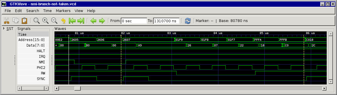
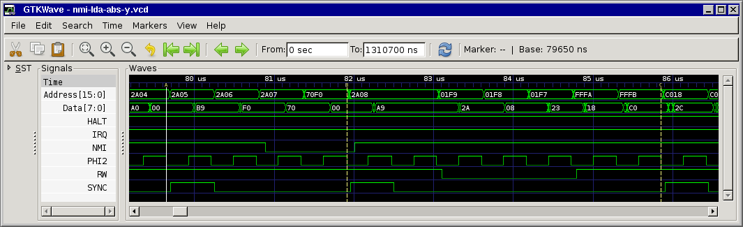
only edition). For clarity, here are 3 separate charts showing cycle and address-bus info for the 3 branch possibilities. And you're right; certain bytes (not always opcodes) do get discarded:
[...]
Note that the cycles marked *** are almost identical, but one is a T0 state (opcode fetch) and the other is not. And this is when our interrupt may get deferred!

Agreed, this is also how I understood the (brief) docs. Still I don't understand why the interrupt is deferred... At first we thought that the CPU kind of "chained" the next instruction to the branch, but since SYNC is set for the next instruction this means it must be something internal in the CPU, maybe something that's not easily measurable from the outside...

Quote:
I'm not surprised that the optional extra cycle from an indexed data fetch doesn't provoke the symptom. That may alter timing, but (unlike our branch) doesn't create uncertainty about the address of the next opcode.

I think this might be the clue to the solution. Maybe :-)

Quote:
Still, it's rather a puzzle you've uncovered. It would seem to imply that an interrupt would never be recognized if the code stream cosisted of nothing but branches-taken-without-pagecrossing! (A single branch-to-self instruction could execute this way, for example.) Would the interrupt be deferred forever ?!

AtariAge user drac030 had the same idea yesterday, so I checked it:
Image
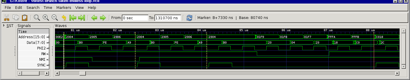
The branch-to-self is executed a second time, then the NMI handler starts. Of course afterwards the CPU is busy branching to the same location again and again, but it doesn't have any impact on interrupt processing.

So, I still guess, it must be the combination of the T2->T0 transition of a branch instruction occurring at the same moment as interrupt servicing would (normally) start.

Since this "bug" has (almost) no bad side effects (compared to a JMP $xxFF, for example), it could explain why it hadn't been noticed before (still, it's strange to discover a new "bug" in a ~35 year old device :-). All instructions are processed as they should be, only one instruction of the main code is executed before the interrupt handler. Then the main code continues at the next instruction. So it's only a tiny shift of 2-6 cycle, but overall execution time is identical (only the absolute times when instructions are executed are shifted a little bit).

I ran across this issue when I did a worst-case cycle analysis of my highspeed SIO code (serial transmission from/to peripherals at ~126kBit/sec).

The Atari SIO protocol is quite simple, the computer sends a command frame (eg "drive 1: read sector 1") to a device, then the peripheral device sends the data frame back (plus some acks and checksums etc.). The critical part here is being able to receive all bytes from the peripheral within time (Pokey really is a beast when it comes to serial I/O - if you are really, really brave have a look at the Pokey serial and IRQ timing details thread over at AtariAge where I documented my findings).

My code does polled I/O and only uses the vertical blank NMI triggered every 1/50 (or 1/60) second for timeout handling and incrementing the clock-tick (which might be used by programs).

According to my calculations I still had one cycle left in the worst case in the vertical blank NMI code, but if I added a single cycle to my code (for example changing a BEQ to a BNE), I ran into very rare transmission problems (using worse case testing, average case was never a problem). I had a single byte missed every 10-60 minutes. Not a big deal, my code worked fine, but I'm a very curious guy :-)

I managed to narrow the parameters (i.e. the exact starting time of a transmission) down so that the error usually occurred within 20-60 seconds, and set timeout so that my miniLA could capture the interesting cycles in it's 120k pretrigger buffer (triggered by the timeout which I managed to set to 1/50 sec - short enough for the logic analyzer's buffer).

BTW: the worst-case scenario looks like this: at first I have a loop that checks if a byte was received:
Code:
        LDA #IMRECV
?GETBY2 BIT IRQST
        BPL ?ERRBRK     ; break key pressed?
        BNE ?GETBY2

It's quite obvious that the longest time this code can take (after receiving a byte) is when the received byte (signalled in IRQST) occurs immediately after the check of IRQST. Of course, what makes testing quite hard, is that you don't know when a byte will be received since you are not on the sending side.

Then, the code has to read the received byte, reset the IRQ and enable the IRQ (in Pokey) again, so it will signal the reception of a new byte. Standard stuff, so far.

Of course, if an NMI (for timeouts etc.) kicks in during this time, the code will be delayed by some time. Still nothing special, you can calculate the maximum time the NMI handler will take.

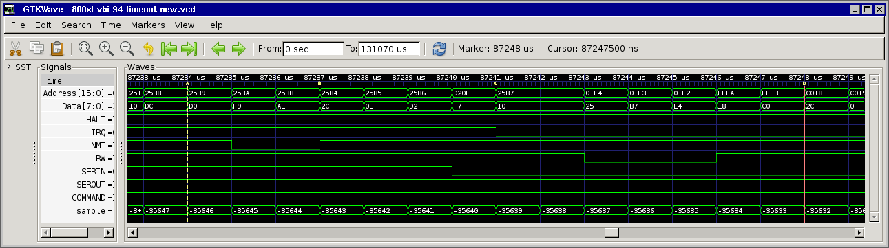
But: the special thing on Atari computers is that the Antic stops the CPU at various times (for doing DRAM refresh and for fetching display data). Display is not an issue here, but DRAM refresh which occurs at cycles 25, 29, 33, ... 59 of each scanline (there are 114 cycles per scanline).

And this refresh stuff, combined with the "interrupt bug" was the crucial point: the "BIT IRQST" could be execued later than I thought (due to the BNE pointing to it, and the interrupt "bug" shifting it), so the last cycle of the critical path (enabling reception/signalling) landed on another refresh cycle, thus was delayed by another cycle and so the allegedly 1-cycle-longer code was 2 cycles longer.

It took my quite a while to figure this out and at first I couldn't really believe what I saw in the logic analyzer captures and thought it must have been a failure in my logic analyzer or that I interpreted the data wrong. After some testing and research I was sure it wasn't me going mad or my logic analyzer dying, but some weird 6502 anomaly...

Quote:
In another thread I look at some unique bus behavior regarding interrupt recognition. An interrupt violates the rule that says the address bus will always increment following a SYNC cycle.

Thanks for the link! I stumbled across this thread before when I was doing some research, but only had a quick glance at it. I'll read through all of it later!

Quote:
ps- the info above, based on notes I dragged out from decades ago, contradicts what's printed in the MOS manual in regard to T2 and T3. IIRC the notes were created based on actual observation (via oscilloscope). I would welcome other observations. What they printed in the manual doesn't look right anyway:
    T0 PC
    T1 PC+1
    T2 PC+2 + offset (without carry) ; (unrealistically?) fast turnaround for this addition to reach the address bus
    T3 PC+2 + offset (with carry) ; What? That's the fully-baked address of the next instruction. We expect that address in the next T0, not in T3

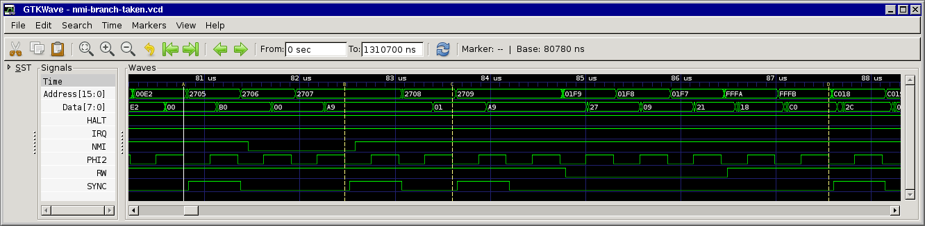
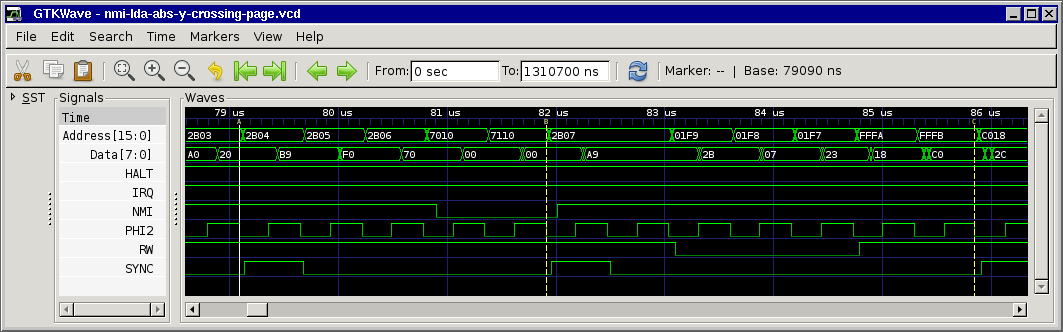
Maybe this screenshot could clarify it a little bit:
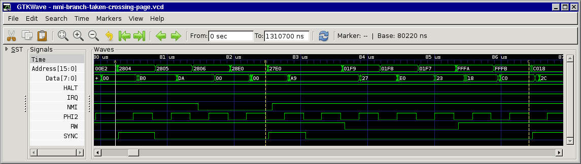
Image
so that's:
T0 PC fetch opcode
T1 PC+1 fetch offset
T2 PC+2 dummy fetch
T3 PC+2+offset (without carry) dummy fetch
T0 PC+2+offset (with carry) code continues

BTW: Just drop me a line if you'd like me to take some more captures with my logic analyzer. It's no big deal for me and I think it's a good thing to document all those (maybe weird) 6502 things once and for all. Unfortunately I only have this Ataris with NMOS 6502 here, no 65C02 or '816s...

BTW2: kudos to all you people on and behind 6502.org, your site contains a wealth of excellent information, I've been reading here (the site and the forums) for several years now, and it has helped me a lot! Even after 25+ years of programming the 6502 there are new and interesting things to learn!

so long,

Hias


Top
 Profile  
Reply with quote  
PostPosted: Sat Sep 04, 2010 4:51 am 
Offline
User avatar

Joined: Thu May 28, 2009 9:46 pm
Posts: 8099
Location: Midwestern USA
After reading your analysis and looking at the logic graphs, I have to wonder if this characteristic was carried over the the 65C02 and 65816. As you say, it appears to be harmless, but does have some perceptible effect on interrupt latency.

Maybe I should build an extra POC unit and send it to you for testing (no logic analyzer here).

_________________
x86?  We ain't got no x86.  We don't NEED no stinking x86!


Top
 Profile  
Reply with quote  
PostPosted: Sat Sep 04, 2010 6:51 am 
Offline
User avatar

Joined: Fri Dec 11, 2009 3:50 pm
Posts: 3326
Location: Ontario, Canada
Welcome to the group, Matthais. I'm somewhat of a newcomer here myself, but on behalf of the gang thanks for your kind words. Thanks also for your observation, which confirms my contention that the MOS doc is incorrect, not merely confusing -- which it also is, in this case! (In fairness I will add that overall I find the MOS Hardware Manual and Programming Manual to be excellent.)

HiassofT wrote:
I ran across this issue when I did a worst-case cycle analysis of my highspeed SIO code [...] According to my calculations I still had one cycle left in the worst case in the vertical blank NMI code, but if I added a single cycle to my code [...] I ran into very rare transmission problems[.] I had a single byte missed every 10-60 minutes.
Well, that answers Garth's question re: what tipped you off! You must have needed some real perseverence to track the symptom back to its cause. Nice work!

HiassofT wrote:
Still I don't understand why the interrupt is deferred...

I don't have a pat answer, but an engineer's mind-set will lead us in the right direction. Here goes:

I believe that the 65xx economizes on silicon by NOT providing specialized hardware to perform the interrupt sequence. Instead, the interrupt is actually an instruction. Like other instructions, it has a unique op-code that's latched into the chip's Instruction Register when SYNC is high. On subsequent cycles the internal PLA pulls whatever strings and levers are required to get the job done. This approach avoids the cost of adding a complex sequencing mechanism solely to implement interrupts.

There is a small amount of extra logic required, but hardly enough to spoil the overall economy. Imagine the Instruction Register as being nine bits wide, not eight. The extra bit I will call the "interrupt-acceptance flip-flop." It is set by NMI (also IRQ and RST) when SYNC is true. Setting IAFF prevents the low 8 bits of the Instruction Register from loading normally from the data bus; instead $00 is loaded. $00 is the opcode for a BRK instruction.

I believe BRK can execute in two slightly different fashions, depending the state of IAFF. If IAFF is clear, the $00 is treated as "real" (ie, as an opcode that came from memory). But if IAFF is set, the $00 is recognized as a substitute that has replaced the opcode that came from memory.

The main difference (I'll ignore the Flags) between the two BRKs is that a "real" BRK increments PC by 2 before pushing it; this sets us up for an eventual RTI to the following instruction. BRK as we know it is a 2-byte instruction; this explains the increment by 2. In contrast, a forced BRK (ie: NMI or other interrupt) is a zero-byte instruction. To ensure an appropriate return the PC mustn't increment at all before being pushed. (Activity on the bus reflects this: interrupt recognition is the only case when the address bus will fail to increment following a SYNC cycle.)

Sorry to be so wordy; the point I'm establishing has to do with timing. I believe an interrupt begins like any other instruction: on T0 -- a SYNC cycle. I don't have a specific answer about the deferred interrupt on the conditional branch, but I do maintain that the interrupt can't commence until the soon-to-be return address appears on the bus. This would be a plausible cause for a deferral, even if the mechanism is unknown. The odd behavior suggests there might be a late-in-the-design, band-aid solution involved.

HiassofT wrote:
it's strange to discover a new "bug" in a ~35 year old device :-).

Strange indeed! I'm glad you brought it to our attention.

-- Jeff


Top
 Profile  
Reply with quote  
 Post subject:
PostPosted: Sat Sep 04, 2010 7:04 am 
Offline

Joined: Wed Feb 03, 2010 2:48 pm
Posts: 9
Hello all,

the detailed description of this 6502 behaviour here is very interesting but it is not new.
See the fpga64 project at http://www.syntiac.com/fpga64.html
and search for "Fixed IRQ/NMI timing of the branch instructions".
Peter has written an absolutely cycle exact 6510 for the chameleon project.There are also some other quirks concerning an IRQ interrupting and NMI or so,I have not try out those things myself.

Greetings,
Vassilis

P.S: I do not want to make the hard work of Hias bad,just to point this thing out.


Top
 Profile  
Reply with quote  
PostPosted: Sat Sep 04, 2010 4:37 pm 
Offline

Joined: Thu Sep 02, 2010 12:34 am
Posts: 36
Location: Salzburg, Austria
BigDumbDinosaur wrote:
After reading your analysis and looking at the logic graphs, I have to wonder if this characteristic was carried over the the 65C02 and 65816. As you say, it appears to be harmless, but does have some perceptible effect on interrupt latency.

The 65816 doesn't seem to be affected (according to the tests of bob1200xl), but the question about the 65C02 still remains unanswered.

Quote:
Maybe I should build an extra POC unit and send it to you for testing (no logic analyzer here).

I had another idea: I have an Atari 800 (which uses the original 6502) at my parent's home, and just remembered that I bought a 65(C?)02 some 20 years ago for a SBC I wanted to create (but never finished it). I'll be visiting my parents next weekend, so I can check if this really is a 2MHz 65C02 and if yes take it all home, put the 65C02 into the Atari and run some tests.

This would save you the time of building a unit and shipping it over to Europe.

so long,

Hias


Top
 Profile  
Reply with quote  
PostPosted: Sat Sep 04, 2010 5:12 pm 
Offline

Joined: Thu Sep 02, 2010 12:34 am
Posts: 36
Location: Salzburg, Austria
Dr Jefyll wrote:
In fairness I will add that overall I find the MOS Hardware Manual and Programming Manual to be excellent.

I can second that, but discovered it's value really late. I had the PDFs on my PC for quite some time, only had a quick glance at them back then, and first had a closer look some weeks ago. I wished I had read these docs a lot earlier, would have saved me quite some time :-)

Quote:
HiassofT wrote:
I ran across this issue when I did a worst-case cycle analysis of my highspeed SIO code [...] According to my calculations I still had one cycle left in the worst case in the vertical blank NMI code, but if I added a single cycle to my code [...] I ran into very rare transmission problems[.] I had a single byte missed every 10-60 minutes.
Well, that answers Garth's question re: what tipped you off! You must have needed some real perseverence to track the symptom back to its cause. Nice work!

Most of the work was analyzing the Pokey. Some specifics were unclear, unprecise and/or documented wrong, so I started to do my own tests some 1.5 years ago. I discovered several important things and got my code to work. But some (timing) details still remained unclear. I tried to do a worst-case cycle analysis but failed miserably (calculating the maximum cycles of the interrupt handler was quite easy, but the rest is quite difficult because Antic halts the CPU quite often, and at different times, to fetch display data from RAM). The result of the analysis was that my code couldn't work at all, so I gave up on it.

This summer I picked up my work, optimized my code further, and did some more analysis. I hadn't expected to open this big can of worms, though. This monday I tracked it down to one last missing cycle, and on tuesday I knew it was this "interrupt bug". So tracking down this specific issue wasn't a too big deal.

I still have to do the worst-case analysis of what's going on during screen access and also have an idea how I could simplify the calculations (with a little helper program).

Quote:
I don't have a pat answer, but an engineer's mind-set will lead us in the right direction. Here goes:
[...]
Sorry to be so wordy; the point I'm establishing has to do with timing. I believe an interrupt begins like any other instruction: on T0 -- a SYNC cycle. I don't have a specific answer about the deferred interrupt on the conditional branch, but I do maintain that the interrupt can't commence until the soon-to-be return address appears on the bus. This would be a plausible cause for a deferral, even if the mechanism is unknown. The odd behavior suggests there might be a late-in-the-design, band-aid solution involved.

Very interesting thoughts! I guess I'll have to think about it for a while.

so long,

Hias


Top
 Profile  
Reply with quote  
 Post subject:
PostPosted: Sat Sep 04, 2010 5:32 pm 
Offline

Joined: Thu Sep 02, 2010 12:34 am
Posts: 36
Location: Salzburg, Austria
nichtsnutz wrote:
the detailed description of this 6502 behaviour here is very interesting but it is not new.
See the fpga64 project at http://www.syntiac.com/fpga64.html
and search for "Fixed IRQ/NMI timing of the branch instructions".
Peter has written an absolutely cycle exact 6510 for the chameleon project.There are also some other quirks concerning an IRQ interrupting and NMI or so,I have not try out those things myself.

Thanks for the link! I knew about the fpga64 project before, but not that they also ran into this "interrupt bug".

I did some searching with google and discovered that some NES guys also ran into this issue in June:
http://nesdev.parodius.com/bbs/viewtopic.php?t=6510

I think we should maybe add a section to the (excellent, BTW) "Investigating Interrupts" document when we finished the 65C02 tests. Garth, what do you think about it?

Quote:
P.S: I do not want to make the hard work of Hias bad,just to point this thing out.

No problem, actually I couldn't really believe that a bug in such a widely used CPU hadn't been noticed before for all this time.

so long,

Hias


Top
 Profile  
Reply with quote  
 Post subject:
PostPosted: Sat Sep 04, 2010 6:07 pm 
Offline
User avatar

Joined: Fri Aug 30, 2002 1:09 am
Posts: 8406
Location: Southern California
Quote:
I think we should maybe add a section to the (excellent, BTW) "Investigating Interrupts" document when we finished the 65C02 tests. Garth, what do you think about it?

I was thinking it would be appropriate, but didn't want to put much time into it. At least one of my cartoons there is terribly outdated now (maybe that just adds to the humor?), and I never did finish getting information on some processors' interrupt-sequence lengths for the end. Maybe I could just add a link to this discussion, as the topic goes beyond the basics that the article was intended to address to help beginners get going with interrups.

_________________
http://WilsonMinesCo.com/ lots of 6502 resources
The "second front page" is http://wilsonminesco.com/links.html .
What's an additional VIA among friends, anyhow?


Top
 Profile  
Reply with quote  
Display posts from previous:  Sort by  
Post new topic Reply to topic  [ 49 posts ]  Go to page 1, 2, 3, 4  Next

All times are UTC


Who is online

Users browsing this forum: No registered users and 0 guests


You cannot post new topics in this forum
You cannot reply to topics in this forum
You cannot edit your posts in this forum
You cannot delete your posts in this forum
You cannot post attachments in this forum

Search for:
Jump to: