Joined: Fri Aug 30, 2002 1:09 am
Posts: 8428
Location: Southern California
|
Clarifications added Jan 8, 2023.
This post is the official 65SIB spec that does not require reading the many prior pages. If there's ever a new version, it can go in a separate post, and I'll link to it in this post.
I tried to put in several helpful links and pictures. In contrast to some very sterile specifications I've read, I intentionally gave some examples, since examples go a long way in helping to understand things, as well as some of the reasoning behind parts of the spec..
--------------------------------------------------------------------------------
Introduction
65SIB, or 6502.org Serial Interface Bus, is an external synchronous-serial bus which, although geared primarily around SPI (and QSPI), can also be used for Microwire devices, daisy chains of dumb shift registers like the 4094, 4021, 74HC165, and 74HC595 (which allow hundreds or conceivably even thousands of bits of I/O at a single 65SIB address), as well as for 3- and 4-wire synchronous-serial interfaces that are SPI-like but different enough that they can't actually be called SPI. All these similar interface types can be mixed on 65SIB, with your controller software knowing how to communicate with each device.
There is a brief text description of several serial protocols here. The 65SIB-development forum discussion can be accessed starting here. Related, the spec. for the proposed SPI-10 hobbyist-friendly connector standard for tiny SPI modules is here, and the spec. for the proposed I2C-6 connector standard for tiny I²C modules is here. Some here on the forum have built these into their SBCs.
The best way to understand data transactions on SPI or one of these other interfaces is generally to examine the data sheet of an IC you are interested in. The wide range of possibilities should quickly become clear.
There are thousands of ICs on the market that communicate by SPI and the other synchronous-serial interface methods mentioned above:
- flash memory, including SD and MMC cards
- RTC (real-time clocks, ie, time-of-day clocks)
- digital potentiometers
- relay drivers
- EEPROM in 8-pin DIPs
- temperature sensors
- A/D converters (ie, analog-to-digital)
- D/A converters (ie, digital-to-analog)
- display drivers
- keypad scanners
- UARTs
- stepper-motor controllers
- USB interfaces
- general-purpose I/O bits
- programmable-gain amplifiers
- signal generators
etc.. You get the idea.
The synchronous serial interfaces are normally used to reduce the number of pins and connections required to interface ICs to each other on the same board. The "synchronous" part of "synchronous serial" is nice because neither the sender nor the receiver have any need for a strict time base like UARTs need, because the shift rate is governed by an additional line, the clock line, which is toggled at any convenient rate that both the sender and receiver can handle, even if that rate is very inconsistent.
65SIB takes the SPI and similar interfaces and makes them an external bus, similar in purpose to IEEE-488 (HP-IB or GPIB). 65SIB aims to make it easier to share designs and conceivably even hardware. It is much more friendly for cobbling together small projects, making your own equipment to be controlled by your 6502 (or other) home-made computer. It specifies a standard connector and other characteristics for compatibility across many synchronous-serial device types. The data transfer protocols are mostly specified in the data sheets of individual ICs you wish to connect. With the addition of the CONF\ (configuration) line, 65SIB allows higher complexity levels of plug-and-play, nested sub-buses, and the like (which have not been thoroughly defined yet), but does not require such complexity levels, and indeed they can be totally ignored by basic users.
Connectors and Cables
65SIB uses very inexpensive connectors and cables. The 65SIB devices use 20-pin headers of .025" square posts that insert directly into common perfboard with holes on .100" centers, and the IDCs get pressed onto ribbon cables in a matter of seconds with a small bench vise or similar tool.
Here's an inexpensive 20-pin plain soldertail header. It is acceptable, but not preferred.
Attachment:
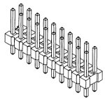 20pinNoShroud.jpg [ 11.63 KiB | Viewed 2557 times ]
Below is a 20-pin keyed & shrouded header with ejector hooks. It is preferred over the plain pin header above because the keyway accommodates the key in the IDC shown further down so it cannot be plugged in backwards or offset, and the ejector hooks not only hold the IDC in but more importantly, aid in unplugging it without bending the pins.
Attachment:
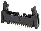 Header20.jpg [ 4.73 KiB | Viewed 2557 times ]
With a little effort, you can find these pin headers available in wire-wrap versions as well.
Here is a 20-position keyed insulation-displacement connector, or IDC. The "insulation displacement" is the wire spacing given by the insulation on the ribbon cable which puts the wires on .050" centers to go with the two rows of pins on .100" centers.
Attachment:
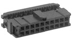 IDC20.jpg [ 4.61 KiB | Viewed 2557 times ]
To mount the IDC on the ribbon cable, you just put the ribbon in the slot visible at the back and press the back onto the IDC with something like a small bench vise. The prongs underneath bite through the ribbon's insulation and connect all the wires at once, making a finished product that looks something like this:
Attachment:
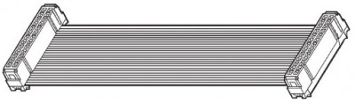 ribbonIDC20.jpg [ 22.45 KiB | Viewed 2557 times ]
Addressing
There are seven active-low device selects, labeled SEL1\ through SEL7\ in the pinout below. (Pin header pinouts, BTW, are viewed from the top of the pins, not from the solder side of the board.) Only one select line goes down at a time. Up to seven devices can be on the bus at once using only primary addressing. (Optional hubs and sub buses, which can add far more, will be discussed later. Most users won't need them.) Having the individual select lines means that device construction becomes easier since devices don't need additional ICs to decode addresses from fewer lines.
A practical setup for the master is to have three bits of a port on, say, a 6522 be dedicated to 65SIB address, then use a 74HC138 to convert those three bits to the seven 65SIB select lines, reserving one '138 output for "select none" rather than using yet another bit for the enable. (This '138 is on the master, not each device.) Another possibility is to use a '137. It's kind of like a latched '138, so you give it the desired address and then put a low pulse on the GL\ line to latch it, so then you can use the lines feeding the 137's address inputs for other things too.
Figure 1. The 65SIB connector:
Code:
+----+----+
CONF\ | 1 | 2 | GND
+----+----+
CLK | 3 | 4 | GND
+----+----+
MOSI | 5 | 6 | GND
+----+----+
MISO | 7 | 8 | +12V
+----+----+
IRQ\ | 9 | 10 | +12V
+----+----+
SEL1\ | 11 | 12 | SEL2\
+----+----+
-12V | 13 | 14 | SEL3\
+----+----+
SEL4\ | 15 | 16 | GND
+----+----+
SEL5\ | 17 | 18 | SEL6\
+----+----+
GND | 19 | 20 | SEL7\
+----+----+
There is an automatic guarantee that no two devices will occupy the same address. The address of each 65SIB device depends on the position it occupies in the daisychain of devices. The device can also occupy more than one address if needed (as explained below), and the addresses of the devices down chain from it will simply be bumped up that much further, as shown in the example in figure 2:
Figure 2. Example of 65SIB daisychain where one or more devices need more than one address:
Code: +------------+ +-------------------+ +--------+ +--------+
| | | | | | | | Nothing
| Controller |---->| Addr 1 --> Addr 2 |---->| Addr 3 |----> Etc.---->| Addr 7 |----> further
| | | | | | | | will get
| | | | | | | | selected
+------------+ +-------------------+ +--------+ +--------+
Master Device A Device B <Add'l devices>
double flash drive display programmable power supply,
(needs two addresses temperature sensors,
in this example) other data acquisition, etc.
If a device—let's call it device A for this discussion—needs only one address, it will use only SEL1\ on its input connector (which goes toward the controller). The SEL2\ on its input connector then gets wired to the SEL1\ on the output connector (which goes to devices further down the daisychain), the SEL3\ on the input (controller) side goes to the SEL2\ on the output side, and so on, shifting each one down one position. The SEL7\ gets pulled up to +5V through a 4.7K resistor (the resistor avoids damage if there's ever a short) and has a .1µF to ground at the connector.
If there is more than one 65SIB device, the next device down the daisychain from device A, ie, device B now, also looks at its SEL1\; but device A above shifted all the SELect lines down a position, so the controller sees device B as residing at address 2, not 1. If a device uses two addresses, it will shift the SELect lines down two positions instead of one, and pull SEL6\ and SEL7\ outputs up to +5V through a 4.7K resistor, and put a .1µF from there to ground at the output connector.
Some non-SPI devices will need an inverter on their input from their corresponding 65SIB SEL\ line to make them compatible. If you want to put devices with other protocols not mentioned here on 65SIB, proceed with caution. It may be possible, but probably not the most practical. My I²C interface for example is separate. André has an SPI page that includes using SD cards and MMC cards on SPI. Maxim has an ap. note on putting SD cards on SPI here.
Power Available on the Bus
65SIB devices that don't have major power draw can get their power from the bus using as little as a 78L05 3-pin regulator in a TO-92 package instead of needing their own power supply. The bus can carry up to an amp on its +12V supply and half an amp on its -12V supply, provided the master can supply that much current. These are combined totals for all the 65SIB devices on a single 65SIB port. (You could even have a transparent 65SIB device that supplies the power to both the master and the other devices without taking up any addresses if desired; but it should be designed so that there is no damage if power comes from more than one source on the bus.) Devices with heavy current requirements should have their own separate supply instead of relying on the ribbon cable.
Some devices may need these higher voltages and the negative voltage for op amps, supertwist LCD backplane, D/A converters with outputs that can go both above and below ground, and other things, and it is easier to get 5V or 3.3V or 2.5V from 12V than vice-versa, which is why ±12V are provided. If we had put 5V on it, going through the daisychain of ribbon cables and connectors might mean the 65SIB device(s) at the end of the line get a "+5V" that's well below 5V, depending on total current draw. Putting a regulator on each device, to go from the higher voltage down to 5V, solves this problem. Exact voltage here is seldom critical, so don't sweat it. There's no specified tolerance so far, but based on experience, I would recommend ±9V as a minimum. Some RS-232 line drivers specify 13.5V max. My PIC programmer needs 13V for Vpp, but that came along before we devised 65SIB.
Every 65SIB device should have .1µF monolithic ceramic capacitors or chip MLCC's between the power pins and ground at both the 20-pin connectors. Any leaded capacitors should be mounted with the leads as short as possible, for minimum inductance.
Signal lines
The three 1-bit lines MOSI (master-out, slave-in), MISO (master-in, slave-out), and CLK (the shift clock issued by the master), and the individual SELect lines (seven of them on 65SIB) are discussed in the SPI specification linked at the top of this discussion, and as mentioned, also work for Microwire, dumb shift registers, and some other synchronous-serial interfaces which are close to SPI but not quite 100% SPI-compatible. There is no need to add much to those discussions here. (Note that SELect lines might be called CS (for "chip select") or SS (for "slave select") in those specifications, or LOAD/SHIFT or similar for devices that are a dumb shift register or little more than that.) There's also the IRQ\ (interrupt request) line and the CONF\ (configure) line.
These lines will all have 5V logic levels. That's not to say every 65SIB device needs to be able to output nearly 5V for a logic "1", but for widest compatibility, the master should, and it should recognize anything over 2V (TTL logic "1") as a valid logic "1" coming from devices.
If you need to adapt it to a different level on the 65SIB device, logic level translators are easy to add since none of the lines are bi-directional. Even open-collector LM339 comparators or 74LS07 open-collector buffers can be used for this. (There are some tips on getting multi-MHz speed out of an LM339 in the first few posts on this topic page.) MISO outputs from devices can be open-collector (or open-drain) if the bus capacitance (which will increase as connection length increases) is low enough that you can still operate at the desired bit rate with the 3.3K or 4.7K pull-up resistor to +5V resident at the master. Devices with totem-pole MISO drivers that can pull up as well as down can still be used, since no more than one device at a time will be selected, and non-selected devices' MISO outputs will be high-impedance. A slower device will not keep faster devices from operating at their full speed or at the fastest speed the master can work, although long cables might. This specification will not dictate a maximum cable length; but if you need a super long one, you may have to do some tests and measurements to find out how much you will have to reduce your data rates to preserve integrity. Additionally, note that some ICs might specify a minimum clock input slew rate. If it cannot be met with long connections, the IC's clock input should be fed through a Schmitt-trigger buffer.
The master should have pull-up resistors of 3.3K or 4.7K on MISO and IRQ\, and 22K to 47K on other signal lines that it does not drive to a valid logic state at power-up before the port is set up by software. The reason for MISO's strong pull-up is to permit open-collector outputs on 65SIB devices without unduly reducing their maximum data rate. IRQ\ is a wire-OR line that can be pulled down by any device set up for generating interrupts. It works the same as the IRQ\ wire-OR line in a 6502 system (at least back when all 65xx peripheral ICs had open-collector IRQ\ outputs), although the master should have a way to block 65SIB interrupts when desired, without blocking interrupts from its own onboard peripheral ICs. MISO of course is never driven by the master, but it should not be left floating. With the input-protection diodes on CMOS parts, the weak pull-ups shouldn't ever cause any damage to non-powered-up devices. Pull-up resistors should not be added to the devices themselves, since differing numbers of devices daisychained can produce widely differing loads on shared lines.
CONF\ line
The CONF\ line is primarily intended for auto-configuration-capable devices. The CONF\ line is made low, followed by lowering the device's SEL\ line, then raising the SEL\ line again. Then as long as the CONF\ line remains low, the device remains selected but it knows that the controller is looking for information about what it is, what it can do, how fast it can take or dish out the data, volume labels, etc., and wants to configure it. This allows the added intelligence for those devices where it's appropriate, but does not obligate any device to have that level of intelligence. If the 65SIB device at the address being polled does not have the intelligence, it won't respond or be bothered, because there were no clock edges between its falling and rising SEL\ edges. If the controller polls an address that has no such intelligence, there will simply be no answer, and the controller moves on to the next one.
The software protocol for auto-configuration and polling is yet to be determined by Samuel Falvo. He started this forum topic for it.
The CONF\ line happens to be useful in other ways too though. A few devices, whether SPI or otherwise, have an extra input that can take advantage without interfering with CONF\'s original intent. I have an SPI graphics LCD for example that has a 1-bit RS (register-select) input, to select data versus instruction registers. If you have no devices with this intelligence, obviously there's no need for the controller software to support auto-configuration; but the controller should still be able to raise and lower that bit for the other uses.
When the controller does not use the CONF\ line and associated intelligence to determine the 65SIB address of the devices that might be connected on it, you will have to either connect (daisychain) the devices in the order your software is written to address them in, or connect them as desired and then tell the software where to find them. < Note to self: Give examples! * * * * * >
Extending the intelligence (optional, not required)
Mentioned above were hubs, sub-buses, and intelligent front ends (IFEs).
The hub is for extending the number of addressable devices when you might need more than the seven allowed by primary addressing. An example of an anticipated need is the scenario where you have one piece of 65SIB lab equipment with several serial devices on it, but you don't want the one piece of equipment to eat up all the available primary addresses. The solution then is to put a 65SIB hub in this piece of equipment. The hub takes only one primary address but has its own 65SIB sub-bus behind it with the same specifications and its own seven addresses (or conceivably more, if they don't need to go out on a standard 65SIB ribbon to other pieces of equipment). The hub in this example is a dedicated hub. You could even add one or more other hubs on that sub-bus, to get more addresses, nesting virtually without limit except that more nested levels will require more overhead.
A non-dedicated, general-purpose hub will have a sub-bus connector identical to the master's own 65SIB connector, and accepts, on its 65SIB sub-bus, any 65SIB device that can go on the master's own 65SIB. The only caveat is that to talk to these other 65SIB devices, the master has to initially talk to the hub, as if making a phone call by talking to the operator first, before the days of direct-dial. Once the connection is established, the operator tunes out.
The preliminary method for the master to communicate with a device on a sub-bus is listed here (post at the top of the page). Again, software protocol is yet to be determined. It is anticipated that since hubs need the microcontroller anyway, they will always have the autoconfiguration intelligence.
An intelligent front end, or IFE is like the sub-bus but it is not particularly for adding more devices, but instead to give the auto-configuration and other benefits to an otherwise non-intelligent device.
Imagine this scenario for one of the other benefits: You have an SPI flash memory with 1KB or 2KB buffers, and they must be read or filled in their entirety all in one SPI transaction. Now you have something else on the 65SIB that urgently needs service; but if you stop the data transfer to or from the flash memory's buffer, and then come back to it later, you have to start over. Clearly, you could run into a situation where you may never finish that transfer! The IFE can put the flash on "hold," leaving the flash's CS\ low (true) but isolating the flash from the clock and data lines while you service something else. The IFE does not de-select the flash when its SEL\ line goes up; but when the SEL\ line falls again, the IFE knows the first info the master will send is for the IFE itself, and two of the possible instructions to it then are to de-select the flash, or to re-connect the master back to the flash to resume the transaction, and quit listening in.
The hub and the IFE are basically the same, but the latter is basically only to add intelligence to a single device. They could be identical in circuitry, both having a 74HCT125 quad tri-state buffer and a microcontroller with a slave SPI port. The IFE's software however would give autoconfiguration information about the one device that its sub-bus is committed to and how it operates with it. Other sub-bus SEL\ lines would go unused.
The exact instructions for hubs and IFEs are yet to be defined.
My intention, if I ever get around to it, is to come up with an intelligent front end and sub-bus controller using a PIC microcontroller, write the software, and publish the whole thing for others to use freely.
65SIB features, design goals, and a few limitations:
- Accommodate thousands of synchronous-serial ICs on the market.
- simple, hobbyist-friendly hardware and software, unlike USB
- Devices can range from dumb as a 74HC165 shift register to very intelligent.
- no tight timing requirements like UARTs have
- up to seven devices on the bus with primary (standard) addressing, and and almost limitless number with optional hubs
- Each device has two connectors, input and output, so they can be daisychained. The controller needs only one, ie, output to the first device. "Input" and "output" here refer to control, not signal direction, as the MISO and IRQ\ lines carry signals toward the controller.
- Connectors and cables are inexpensive and easy to assemble.
- Connectors fit into common perfboard with holes on .100" centers, unlike RJ-11, DB-9, DB-25, etc..
- 65SIB device addresses are automatically unique, avoiding bus contention or any need to set addresses like IEEE-488 requires.
- Since there are no bi-directional lines, voltage translation for differing logic levels is easy.
- For signal integrity, every signal line on the ribbon cables is next to a ground or virtual ground, and CLK, MOSI, MISO, and IRQ\ are flanked by grounds on both sides.
- Interrupt support is available with a single wire-OR active-low IRQ\ line.
- There is only one controller on the bus (not just one at a time). Control cannot be passed to the devices.
- Cables can be up to dozens of feet long, depending on how fast you need to run data. 65SIB is not designed to reach the 160Mbps+ speed that some SPI ICs can achieve; but a few hundred kbps is no problem even with bit-banging on a home-made 6502 computer.
- It is designed to simplify the construction of minimal devices as much as possible. Ideas for reducing the number of ribbon conductors were discussed but discarded because of the added hardware this would have required on each 65SIB device.
- Most 65SIB devices will use little enough power that they can be powered off the bus so they won't need their own power supply.
- Auto-configuration and other intelligent functions can be accommodated, but are not required.
- Hot-plugging is not supported. This limitation is due to the commonly available inexpensive connectors. You could however make the controller able to shut down the power to the 65SIB and pull all the lines low or float them, and tell the user that it's ok to (dis)connect devices now, without shutting down the controller.
Connecting to your SBC
Daryl sells an SPI IC made to go on the 6502 bus. He calls it the 65SPI (not to be confused with this bus, the 65SIB). The forum discussion he entertained in the development starts here. You can also bit-bang through a 6522 VIA or similar chip. The VIA has a shift register (SR), but although it has modes that are close to SPI, it's not a match unfortunately. Bit-banging allows all the SPI modes as well as other protocols mentioned earlier. Some ICs' data sheets may just call them "3-wire serial" or "4-wire serial" when they look like SPI but aren't quite truly SPI. Bit-banging is one way to make sure you can interface to these as well.
There's a sample 6522 VIA interface circuit at http://wilsonminesco.com/6502primer/pot ... ITBANG_SPI, with accompanying 65c02 assembly-language example of bit-banging SPI on 65SIB with a 6522 VIA at http://wilsonminesco.com/6502primer/SPI.ASM . (This does not use Daryl's 65SPI chip, since I didn't have room left for it on my SBC.)
Facilitating construction
After we developed 65SIB, I made a peripheral with the small graphic LCD and an SPI flash, and found it was a lot of work to wire up the connectors, regulator, and do the voltage translation to 3.3V. I decided to make a breakout PCB that takes care of all that, and has lots of stuffing options for voltage regulators, interfacing to 5V, 3.3V, or 2.5V parts, and more, and offer it to anyone who needs it. It's the WM-4b shown on the front page of my site. The data sheet, with all the information on various stuffing options, is at http://wilsonminesco.com/65SIBbreakout/ ... -31-22.pdf .It looks like this:Attachment:
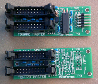 topViewSmall.jpg [ 56.72 KiB | Viewed 2557 times ]
_________________ http://WilsonMinesCo.com/ lots of 6502 resources
The "second front page" is http://wilsonminesco.com/links.html .
What's an additional VIA among friends, anyhow?
Last edited by GARTHWILSON on Tue Jan 03, 2012 9:16 pm, edited 4 times in total.
|
|


