Page 5 of 8
Posted: Thu Jan 26, 2006 5:16 am
by GARTHWILSON
Why not use the pins from a machine pin socket?
I expect they would be so thick so as to damage at least
some sockets the module would get plugged into. Another choice would be a 40-pin DIP header, since those are specifically made to go into DIP sockets without damaging them.
Posted: Fri Jan 27, 2006 12:43 pm
by debounce
Why not use the pins from a machine pin socket?
I expect they would be so thick so as to damage at least
some sockets the module would get plugged into. Another choice would be a 40-pin DIP header, since those are specifically made to go into DIP sockets without damaging them.
Why not solder two rows of jumper posts (or wirewrap terminals for more clearance); then push these into a DIP socket which then plugs into the motherboard. The free socket can only marry once with the posts but many times with the motherboard.
A few professionals / collectors prefer this, often putting a DIP socket onto bare posts first thing before installation. It reinforces the jumper pins and of course, the socket can be replaced if its pins bend or snap. Recently someone on the BBC Micro Mailing List complained about connectors snapped off from a potted module (sadly preventable.)
Turned pin DIP sockets seem okay for insertion, the tips aren't that much wider than IC legs. You could go for formed pins to be sure, but some designs use single-ply metal on the legs, which bends
very easily and is obviously intended for solder work.
Posted: Thu Jan 21, 2010 7:41 pm
by BigEd
Why the buffers as the 65816 can tristate itself? My idea ... when not accessing the original hardware, the 65816 could run at higher speed.
... after several seconds the C64 crashed. Strange enough when using a FC3, it ran reasonably well...
Hi Ruud
richarde and myself are recapitulating these adventures. We have a just-65816 board which runs OK in an Oric (this is confusing: we think we ought to need to connect BE to PHI2, but doing so stops it working) and we also have a 65816+RAM+CPLD board which allows the 65816 to run much faster than the host. It runs nicely on an Acorn BBC, but doesn't (yet) work on the Oric. There's
a thread here. We do have a C64 but haven't tried to do anything with that (yet.)
I had to look up FC3 - it seems to be a ROM cartridge. It could only be changing the timings by loading the bus, presumably?
Cheers
Ed
Posted: Fri Jan 22, 2010 12:30 pm
by BigEd
Why not use the pins from a machine pin socket?
I expect they would be so thick so as to damage ... Another choice would be a 40-pin DIP header, since those are specifically made to go into DIP sockets without damaging them.
Why not solder two rows of jumper posts (or wirewrap terminals for more clearance); then push these into a DIP socket which then plugs into the motherboard.
Our approach was to use a 40-way edge connector, ribbon cable and 40-pin header - it works well, and gives flexibility as to mounting a board left side, right side, vertically or upside down.
(I can't quite bring myself to cut off the extra cable, in case I want it longer some day! At 50pF/m I think I can get away with it.)
Posted: Mon Aug 09, 2010 8:08 pm
by GARTHWILSON
Not the same thing we were talking about with everything on a 40-pin DIP hybrid, but André Fachat has carried out the idea on a bigger board. See his page about it
here . He mentioned it in
this post in the topic Programming-->"Code optimization !?"
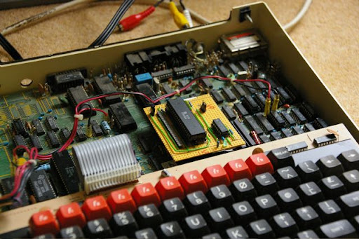
Two posts under that, BigEd shows another project with a smaller board (which does not appear to be what's shown above), but still not a 40-pin DIP hybrid, and gives a picture:
Posted: Mon Aug 09, 2010 9:50 pm
by 8BIT
I recently built a board that would plug into a CPU's 40-pin DIP socket.
I found these round-pin headers from Mil-Max (Figure A):
http://www.mouser.com/catalog/catalogUSD/642/1552.pdf
You can get them at mouser.com - part # 575-643506
It includes a strip with 64 pins but you can snap off the quantity you need.
The cost is a little high at $8.26, but they worked very well for my daughter board.
Daryl
Posted: Mon Aug 09, 2010 9:57 pm
by fachat
In Germany I get these pin headers at reichelt
http://www.reichelt.de/?ACTION=3;GROUP= ... f97dfc9bc5
I still place a standard socket underneath it (not the rounded ones, but the ones with the flat pins), that I can easily replace if it breaks
André
Posted: Sat Sep 11, 2010 9:07 am
by GARTHWILSON
Daryl, your links on previous pages of this topic are dead. Do you still have the images?
Posted: Sat Sep 11, 2010 3:22 pm
by 8BIT
Daryl, your links on previous pages of this topic are dead. Do you still have the images?
I've updated the links and yes, I still have all of the support files. Those Milmax pins from Mouser will work for this board too.
http://sbc.rictor.org/support/conv.html
Daryl
Posted: Sat Sep 11, 2010 8:12 pm
by GARTHWILSON
http://sbc.rictor.org/support/conv.html
What a nice layout! and yet now unfortunately it looks like WDC is no longer selling the PQFP.
Posted: Sat Sep 11, 2010 8:58 pm
by 8BIT
I noticed that too. However, a PLCC might fit without a socket. I'll have to look to see if the pinout has the orientation and spacing. If not, I can probably update the layout.
Seems there's no getting away from SMT these days.
Daryl
Posted: Sun Sep 12, 2010 2:18 am
by 8BIT
Pin numbers are different but the actual pin fuction's relative to the top center pin of the chip is the same. However, the chip size is too big to fit between the 0.6" DIP pins.
Doesn't look promising that I will be able to keep the board size as small.
Daryl
Posted: Sun Sep 12, 2010 4:02 am
by kc5tja
Where do you acquire the pins that fits the original 40-pin socket? I know I've found wire-wrap posts before, but those really don't fit well in most sockets (too big, and can damage the socket).
Thanks.
Posted: Sun Sep 12, 2010 4:59 am
by 8BIT
See my post 1/2 way down this page (8 up from this post) - they are milmax posts sold through Mouser.
Posted: Sun Sep 12, 2010 5:45 am
by kc5tja
Not sure how I missed that. Thanks.