I too can confirm that the green 3M ZIFs are poor quality. One came fitted to my programmer, and I have to do the scrape trick too, a lot of the time. I thought that was an isolated incident. I might consider retrofitting a better one now that I know it isn't, because it's a decent programmer, otherwise.
On the other hand, the Aries socket I bought for my previous prototype has served me very well. No failures there, but that's soldered down. I intend to recover it later; that thing was expensive.
POC VERSION TWO
Re: POC VERSION TWO
Not sure if it helps but I've been using an Aries Eject-a-dip for my ROMs which is a bit cheaper than their ZIF sockets.
Haven't had any problems for the last couple of years with these, It also does a good job of holding the DIP plug in for my rom emulator

http://au.element14.com/aries/28-c182-1 ... ject-a-dip
Haven't had any problems for the last couple of years with these, It also does a good job of holding the DIP plug in for my rom emulator
http://au.element14.com/aries/28-c182-1 ... ject-a-dip
-
BigDumbDinosaur

- Posts: 9425
- Joined: 28 May 2009
- Location: Midwestern USA (JB Pritzker’s dystopia)
- Contact:
Re: POC VERSION TWO
LIV2 wrote:
Not sure if it helps but I've been using an Aries Eject-a-dip for my ROMs which is a bit cheaper than their ZIF sockets.
Haven't had any problems for the last couple of years with these, It also does a good job of holding the DIP plug in for my rom emulator
http://au.element14.com/aries/28-c182-1 ... ject-a-dip
Haven't had any problems for the last couple of years with these, It also does a good job of holding the DIP plug in for my rom emulator
http://au.element14.com/aries/28-c182-1 ... ject-a-dip
x86? We ain't got no x86. We don't NEED no stinking x86!

Re: POC VERSION TWO
BigDumbDinosaur wrote:
Unfortunately, it hogs quite a bit of space on the board, as clearance has to be provided for the ejection levers. It won't fit on any of my POC designs.

-
BigDumbDinosaur
- Posts: 9425
- Joined: 28 May 2009
- Location: Midwestern USA (JB Pritzker’s dystopia)
- Contact:
Re: POC VERSION TWO
BigEd wrote:
BigDumbDinosaur wrote:
Unfortunately, it hogs quite a bit of space on the board, as clearance has to be provided for the ejection levers. It won't fit on any of my POC designs.
x86? We ain't got no x86. We don't NEED no stinking x86!

Re: POC VERSION TWO
BigDumbDinosaur wrote:
BigDumbDinosaur wrote:
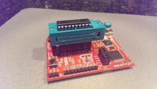
In future endeavors of this kind, I will solder the ZIF socket into the prototype's PCB instead of piggybacking it on the ROM socket. The only reason I didn't do that with POC V2 was the frugal Irishman in me didn't want the 15 dollar ZIF socket becoming a permanent part of the assembled unit.
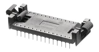
I also found a stash of these on eBay a few years back. I only have about 8 left and don't know where to get more of them, but they are fabulous for EPROMS and endure countless insertions without failing or harming the chip. They are marked only with a stylized Robinson Nugent "RN" - no part number.
Bill
-
BigDumbDinosaur
- Posts: 9425
- Joined: 28 May 2009
- Location: Midwestern USA (JB Pritzker’s dystopia)
- Contact:
POC V2.1 Crashing & Burning
BigDumbDinosaur wrote:
The trouble was coming from an unsuspected place...The [ZIF] socket turned out to have an intermittent connection in it.
After I had replaced the ZIF socket, I discovered I hadn't fixed anything, which sent me into a period of deep thought about what might be going on. Visions of obscure timing issues, excessive bus loading, a flaky 65C816, etc., were dancing in my head. So what I did was remove the ZIF socket, plug the ROM directly into its socket and powered up. Much to my amazement, the unit WOULD NOT RUN, even though it had run before in this configuration. At this point is was clear that there was a hardware issue lurking within.
The next step was to removed the Ø2 oscillator and substitute a much slower one, taking the unit's Ø2 rate from 12.5 MHz down to 4 MHz. Now the unit would boot and /IRQ and RDY activity were back to normal.
At this point, I'm stuck in trying to troubleshoot the unit, as none of the parts I used should have any problems with high clock rates. The slowest item is the 55ns EPROM, which I also used in POC V1.1, which can boot at 15 MHz without the SCSI host adapter in place. Grrrrr!
P.S. The thought just occurred to me that this could be a problem being caused by signal voltage levels. I may have a basic design problem related to TTL vs. CMOS voltage differences.
x86? We ain't got no x86. We don't NEED no stinking x86!
Re: POC VERSION TWO
That's hard to hear BDD. I mean, the initial thought that it was the socket (of all things), was frustrating enough. Having it lead you down on a wild goose chase, that's even worse.
Hope that you can figure it out.
Hope that you can figure it out.

Re: POC VERSION TWO
Overshoots / undershoots / line reflections ?
As you say the components are quick enough for 15 MHz, the logic works as it should, and problems appears with shorter cycle times. As you said the random crashes were still present with the new socket but the system didn't run without the socket it looks as if the sockets impedance/capacitance has a "beneficial" effect.
I think you need to pick up the scope to look how the signals look with/without socket. And on both ends of the bus as well. May be the signals getting worse elsewhere. (I haven't tracked this thread backwards - was it a 4 layer board?)
If it is voltage related you may lower VDD perhaps using one or two diodes. But then 15 MHz might not work just because the voltage is too low and the components getting slower.
Re: POC VERSION TWO
I went back about something like 10 pages in this and did not see anything about thermal testing. Perhaps this random crashing problem is related to a physical flaw - either in one of the chips or in the copper on the board. I've had more than a few 'bad' chips in my life that seem to work 99.9999% of the time, then for whatever reason (usually heat, but sometimes cold or mechanical vibration) just malfunction long enough to derail everything. The same can be said for PCBs - microscopic cracks in traces, bad vias, traces with impurities that act like resistors and even bad trough-hole plating (similar to the bad via). I have seen all of this stuff more than once. If you've not already done it, it might not be a bad idea to put in a few laps around the board with a hot-air gun and a can of freeze spray. Even tapping things with the handle of a screwdriver.
Bill
-
BigDumbDinosaur
- Posts: 9425
- Joined: 28 May 2009
- Location: Midwestern USA (JB Pritzker’s dystopia)
- Contact:
Re: POC VERSION TWO
BillO wrote:
I went back about something like 10 pages in this and did not see anything about thermal testing. Perhaps this random crashing problem is related to a physical flaw - either in one of the chips or in the copper on the board. I've had more than a few 'bad' chips in my life that seem to work 99.9999% of the time, then for whatever reason (usually heat, but sometimes cold or mechanical vibration) just malfunction long enough to derail everything. The same can be said for PCBs - microscopic cracks in traces, bad vias, traces with impurities that act like resistors and even bad trough-hole plating (similar to the bad via). I have seen all of this stuff more than once. If you've not already done it, it might not be a bad idea to put in a few laps around the board with a hot-air gun and a can of freeze spray. Even tapping things with the handle of a screwdriver.
x86? We ain't got no x86. We don't NEED no stinking x86!
Re: POC VERSION TWO
BDD,
in another thread you mentioned that perhaps the output voltage ratings of a CPLD or GAL may cause trouble when a 65Cxxx is the receiver. This would to some extend explain the behavior your POC V2.x shows. Have you considered to replace the CPLD with a piggyback board containing the same CPLD plus AC(T) type buffers for those signals that goes to the CPU?
in another thread you mentioned that perhaps the output voltage ratings of a CPLD or GAL may cause trouble when a 65Cxxx is the receiver. This would to some extend explain the behavior your POC V2.x shows. Have you considered to replace the CPLD with a piggyback board containing the same CPLD plus AC(T) type buffers for those signals that goes to the CPU?

Re: POC VERSION TWO
GaBuZoMeu wrote:
[...] replace the CPLD with a piggyback board containing the same CPLD plus AC(T) type buffers for those signals that goes to the CPU?
In 1988 my 65C02 got six new registers and 44 new full-speed instructions!
https://laughtonelectronics.com/Arcana/ ... mmary.html
https://laughtonelectronics.com/Arcana/ ... mmary.html
-
BigDumbDinosaur
- Posts: 9425
- Joined: 28 May 2009
- Location: Midwestern USA (JB Pritzker’s dystopia)
- Contact:
Re: POC VERSION TWO
GaBuZoMeu wrote:
Have you considered to replace the CPLD with a piggyback board containing the same CPLD plus AC(T) type buffers for those signals that goes to the CPU?
Things would be slightly complicated by the fact that the four data bus connections to the CPLD are bi-directional. So I'd have to use a bus transceiver, e.g., a 74ACT245, for that part of the circuit. The remaining connections (outputs) could go through a 74ACT541 or similar. These devices would add a small amount of prop delay—under 10ns, but that shouldn't be of any consequence.
Dr Jefyll wrote:
Or, alternatively (and as an experiment) try adding some stiff (1K or less) pullup resistors on CPLD signals that go to the CPU.
x86? We ain't got no x86. We don't NEED no stinking x86!
Re: POC VERSION TWO
As an afterthought: Does the CPLD drive the CPU clock input? Assuming the CPLD offers selectable slew rates per pin, and if you haven't already done so, maybe you should try selecting the "fast" setting for the CPLD pin that drives the '816 clock input. I know this won't result in a higher VOH but it might reduce the time spent in transit between the "not zero anymore" voltage and the "kinda sorta one now" voltage. Worth a shot, maybe -- I'm just throwing the idea out there. (The pullup could be used in conjunction with this.)
In 1988 my 65C02 got six new registers and 44 new full-speed instructions!
https://laughtonelectronics.com/Arcana/ ... mmary.html
https://laughtonelectronics.com/Arcana/ ... mmary.html