Page 4 of 10
Re: My project with a w65c265s MCU.
Posted: Wed Jun 03, 2020 1:18 pm
by tokafondo
Hi. I can now start building a
Mensch Microcomputer clone, so I can test myself if I can be able to get this to something done.
Re: My project with a w65c265s MCU.
Posted: Mon Jun 15, 2020 12:15 am
by tokafondo
After a week of hiatus, I've been able to finish soldering the thing.
The w65c265s does use two clocks to boot: a slow 32768hz clock (CLK) and a fast (FLCK) clock, whose speed you can choose up to more or less 8 Mhz.
What's happening right now is that I put a 4,9152 Mhz crystal (as recommended in the data sheet, to be able to generate ceratin baud rates in the serial ports), but I can't get the chip to use it, so it keeps running at 32768hz (0.032768 MHz). It takes about 30 seconds just to output the welcome message trough the seial port.
I put the logic analyzer there and it detects that frequency even in the FCLK circuit... I have to figure now if the capacitors are the right value.
Re: My project with a w65c265s MCU.
Posted: Mon Jun 15, 2020 12:45 am
by thedrip
I have a Mensch Microcomputer (the $18 board) if you need anything from it. I remember the slow/fast clock switching worked just fine.
I haven't done much with it past hooking up the serial port and booting it.
Re: My project with a w65c265s MCU.
Posted: Mon Jun 15, 2020 1:34 am
by tokafondo
Thanks. I actually ordered it and then cancelled because it not having the full address bus exposed, and having the chip select lines populated with leds.
I followed that small board schematics to build my clone, but replaced the ~3.6Mhz clock with a ~5mhz one, and can't get it to run at full speed.
I maybe should have ordered the SXB version...
Re: My project with a w65c265s MCU.
Posted: Mon Jun 15, 2020 3:06 am
by tokafondo
Well... after debugging and debugging... I have now my Mensch computer clone running at 4.9512Mhz.
- Portapapeles01.png (10.73 KiB) Viewed 1864 times
Its a MESS but it does boot.
Re: My project with a w65c265s MCU.
Posted: Mon Jun 15, 2020 7:45 am
by BigEd
Success! Congratulations. Can you say anything about the bugs you found and fixed, which might help future adventurers?
Re: My project with a w65c265s MCU.
Posted: Mon Jun 15, 2020 11:24 am
by tokafondo
Success! Congratulations. Can you say anything about the bugs you found and fixed, which might help future adventurers?
As I choose to put a 4.9152 Mhz clock instead of a 3.6864 MHz one, the capacitor values shown in the w65s265qbx schematics were not the right ones to the crystal I put.
The chip was running all the time at 32768 Hz. I could check that the serial port was actually sending out the welcome screen by attaching the logic analyzer. It was so slow that it took more than 30 seconds!!
I replaced the fixed value capacitors with trimmers and started to slowly adjusting them until they kickstarted the crystal. I can't tell the right values for them, though. They are such a small value that my cheap meter wouldn't give a reliable measure. The range they have is 5-30pf so the value is in there. Also, I suspect that once I start to add chips to the
mix they will need more adjusting, but for now they make the '265 run.
Re: My project with a w65c265s MCU.
Posted: Mon Jun 15, 2020 11:41 am
by tokafondo
The next would be to fit the EEPROM in, and confirm it can be accessed. The documentation shows that the first thing that the '265 embedded ROM does is look for certain bytes in a memory location ($00:8000):
Code: Select all
STATE #1 - "Essential initialization"
- Disable interrupts
- Reset stack
- "Enable External Memory"
- Set BCR to $01        (This turns on external address and data lines.)
- Set PCS7 to $20       (This turns on external chip select: CS5 from the W65C265S.)
- Check location $00:8000-$00:8002 for the string 'WDC', using CS5.
  If the string is there, transfer control to USER program in EXTERNAL MEMORY. (JMP $00:8004)
If
not found, it changes the chip selects and tries again, in the
same memory location, but maybe in a
different external memory chip:
Code: Select all
STATE #2 - "Check External Memory"
- "Enable External Memory"
- Set PCS7 to $30        (This turns on external chip selects: CS4 and CS5 from the W65C265S.)
- Check location $00:8000-$00:8002 for the string 'WDC', using CS4.
  If the string is there, transfer control to USER program in EXTERNAL MEMORY. (JMP $00:8004)
If
not found, it changes the chip selects and tries again, but with a
different memory location ($00:0800):
Code: Select all
STATE #3 - "Check External Memory"
- "Enable External Memory"
- Set PCS7 to $08        (This turns on external chip select: CS3 from the W65C265S.)
- Check locations $00:0800-$00:0802 for the string 'WDC', using CS3.
  If the string is there, transfer control to USER program in EXTERNAL MEMORY. (JMP $00:0804)
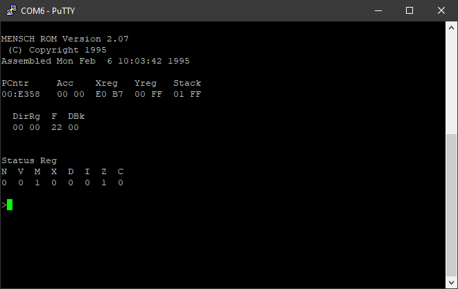
If none of that applies, it then runs the internal rom code and presents the welcome screen.
Code: Select all
MENSCH ROM Version 2.07
 (C) Copyright 1995
Assembled Mon Feb  6 10:03:42 1995

PCntr     Acc    Xreg   Yreg   Stack
00:E358   00 00  E0 B7  00 B0  01 FF

  DirRg  F  DBk
  00 00  22 00


Status Reg
N  V  M  X  D  I  Z  C
0  0  1  0  0  0  1  0
Re: My project with a w65c265s MCU.
Posted: Mon Jun 15, 2020 12:12 pm
by tokafondo
As seen in the previous post, mapping the external 128K EEPROM chip in the $00:0800 memory location would be difficult, so I think the easiest to do is to map it to $00:8000-02:7FFF.
A CPLD could be used to split the EEPROM chip in 32K chunks that would be scattered in the memory map, but I think linear access is better.
What do you think?
Re: My project with a w65c265s MCU.
Posted: Mon Jun 15, 2020 1:56 pm
by Dr Jefyll
Its a MESS but it does boot.
Eeeh! Well, it's possibly not a creation that will appeal to the human eye. But aesthetic issues aren't relevant to electrons.

Congratulations on your success! But please tell me there are some ceramic supply bypass capacitors snuggled up close to the PLCC, and they simply happen not to be visible in the photo. If they are indeed absent then that could very well explain why you had trouble getting the crystal oscillator working (not to mention attracting other squirrely problems in future).

Nice to see someone playing with a bare '265, BTW -- I mean one that's not part of a WDC board. Thanks for sharing!
-- Jeff
Re: My project with a w65c265s MCU.
Posted: Mon Jun 15, 2020 4:14 pm
by tokafondo
Congratulations on your success! But please tell me there are some ceramic supply bypass capacitors snuggled up close to the PLCC, and they simply happen not to be visible in the photo.
Thanks. Yes, there are four capacitors in NSEW of the chip. I'm recycling components from a old DENON audio amplifier. That's why there are different sizes or pacakges.
Re: My project with a w65c265s MCU.
Posted: Thu Jun 18, 2020 2:15 pm
by tokafondo
As I'm planning fitting a SST39VF010 EEPROM, I have now to lower the voltage to 3.3V, because this is currently running at 5V.
The Prolific 2303 clone I'm working with does output both 3.3V and 5V and I can run the board with the 5V, but the clock won't fire up to 4.9mhz at 3.3V.
I have to test with a 78x33 voltage regulator, so I can see if this is a matter of power or if I have to get the same components with different values.
Re: My project with a w65c265s MCU.
Posted: Thu Jun 18, 2020 3:20 pm
by BitWise
As I'm planning fitting a SST39VF010 EEPROM, I have now to lower the voltage to 3.3V, because this is currently running at 5V.
Why didn't you use the SST39
SF010 which is 5V?
Re: My project with a w65c265s MCU.
Posted: Thu Jun 18, 2020 4:00 pm
by tokafondo
It seems working now at 3.3v... Maybe capacitors were still holding 5V charge and that made the whole circuit go crazy.
Why didn't you use the SST39SF010 which is 5V?
The '265 works with a lot of voltages. The EEPROM works 2.7v-3.6v. The EPSON graphic chip I've chosen to work with does it with 1.8v and it's 3.3v I/O tolerant, so If I want to stick so a voltage, it must be 3.3v, so the only voltage conversion would be 3.3v -> 1.8v.
Re: My project with a w65c265s MCU.
Posted: Fri Jun 19, 2020 1:33 pm
by tokafondo
I had a false success yesterday: the thing operating at 3.3V is not stable at all. It seems to me that I'll have to replace the fixed capacitors in CLK (the clock running at 32768Hz) with variable ones, to find the right capacitante for it to start ticking again.