Page 4 of 9
Re: Writing in EEPROM and reading by 6502
Posted: Tue Dec 18, 2018 8:50 am
by BigEd
hitlp, did you ever look at Sync? I think having your logic analyser look at more than just the databus will be very handy. Even with just 8 channels. For example you could watch
SYNC
R/W
A0
A1
A2
A13
A14
A15
And the next step is to take traces of more signals, as overlapping subsets, so you can view them together
SYNC
R/W
A0
A1
D0
D1
D2
D3
SYNC
R/W
A0
A1
D4
D5
D6
D7
Of course, with a tied-off databus that's intended to put in a NOP, but which seems not to be acting like a NOP, you don't need to watch the databus. It seems most likely that you haven't tied it off in the way you intended - some open circuit or swapped pins or shorts or something. I think I'd start with very close inspection, which you have to do without prejudice - write a checklist and then work through it as blindly as you can, assuming nothing.
Edit: watching the reset and interrupt pins might also be useful. A bad reset or a bad clock could cause malfunction. Or bad power.
Re: Writing in EEPROM and reading by 6502
Posted: Tue Dec 18, 2018 1:36 pm
by Chromatix
With a modern CMOS version of the 6502, you'd be able to manually toggle the clock line and observe the behaviour by hand. The NMOS chips have a minimum frequency, however, which complicates matters since you automatically have to deal with high-frequency effects. I do have to question why you're starting a new project with an old chip.
Re: Writing in EEPROM and reading by 6502
Posted: Wed Dec 19, 2018 1:32 am
by hitlp
Hi Guys,
This is the new chapter in this series. According to your tip, I put ceramic capacitors and tried to reduce the size of some wires in the circuit.
I turned it on again and after pressing the reset button, it happens as I attached it. It percore several cycles with A0 equal to half the clock (500 KHz) but then apparently it behaves as it should. However, several more clocks later, and the A0 signal is lost again.
And now? lol
With a modern CMOS version of the 6502, you'd be able to manually toggle the clock line and observe the behaviour by hand. The NMOS chips have a minimum frequency, however, which complicates matters since you automatically have to deal with high-frequency effects. I do have to question why you're starting a new project with an old chip.
Chromatix, my idea is to assemble hardware that is as close to ATARI hardware as possible but of course with all the limitations I have. What kind of difference would these processors have?
Re: Writing in EEPROM and reading by 6502
Posted: Wed Dec 19, 2018 1:50 am
by Chromatix
The 65C02 series corrects a few bugs in the original NMOS 6502, eliminates a number of "undocumented" opcodes that very little software actually used, and adds some new opcodes that are generally more useful. It is also a lot more power-efficient and, especially in the current production version by WDC, is much more flexible in terms of clock input. The 65C02 also correctly responds to RDY being negated during a write cycle; the NMOS 6502 only responds during a read cycle.
The new instructions include BRA (unconditional relative branch), PHX/PHY/PLX/PLY which let you directly stack the index registers instead of having to transfer them via the accumulator, TRB/TSB which allow atomic bit test and (re)set, and STZ which lets you zero memory without having to first zero a register. Using these allowed Acorn to make later versions of the BBC Micro's firmware more compact and faster without changing the clock speed. All unimplemented opcodes on the 65C02 are explicit NOPs, whereas on the NMOS 6502 many of them will lock up the CPU until it is reset.
Generally I would say that the only reason to use an NMOS 6502 these days is when *strict* compatibility with legacy software is required. This could mean timing requirements, or use of undocumented opcodes, or accidental reliance on some of its more obscure bugs.
If you're building a new machine that merely aims at a similar level of functionality to some old example, but doesn't rely on old software, then none of these compatibility concerns should apply to you, and you should use an CMOS CPU. But if you're trying to strictly emulate a particular old machine, then you should be obtaining the circuit diagrams for the original and trying to replicate them faithfully, instead of messing around with a breadboard.
Re: Writing in EEPROM and reading by 6502
Posted: Wed Dec 19, 2018 1:58 am
by GARTHWILSON
Because of the CMOS 6502's many improvements over the NMOS, shown at
http://wilsonminesco.com/NMOS-CMOSdif/ , I would reiterate Chromatix's recommendation that if you don't need compatibility with legacy software, it's usually much better to go with CMOS for new projects. (It won't fix wrong connections though, if that turns out to be what you have.)
Re: Writing in EEPROM and reading by 6502
Posted: Wed Dec 19, 2018 2:03 am
by Dr Jefyll
Thanks for thje additional info, hitlp. The trace of A0 changing its frequency is quite remarkable!
One possible explanation is that the CPU is getting triggered at twice the clock rate. This can happen if the clock signal is not a strong, rectangular waveform but instead has ringing and perhaps insufficient amplitude. This can also produce intermittent results -- which of course is what you're seeing.
I suggest you try to improve the wiring of the clock circuit. Add a bypass capacitor for the 7404 that drives the CPU clock input, and keep the wire for the clock signal short. It may also help to add a pullup resistor from the 7404 output to Vcc. If you still have trouble, please post another photo showing what you've done.
-- Jeff
Re: Writing in EEPROM and reading by 6502
Posted: Wed Dec 19, 2018 2:25 am
by Chromatix
I'd very much like to see the SYNC trace corresponding to that high-frequency A0 transition. The NMOS 6502 has no single-cycle instructions, so SYNC appearing to stay high would be a smoking gun for a Phi2 double-triggering.
Re: Writing in EEPROM and reading by 6502
Posted: Wed Dec 19, 2018 3:06 am
by hitlp
I'd very much like to see the SYNC trace corresponding to that high-frequency A0 transition. The NMOS 6502 has no single-cycle instructions, so SYNC appearing to stay high would be a smoking gun for a Phi2 double-triggering.
I think SYNC is not working as it should be right? lol
Re: Writing in EEPROM and reading by 6502
Posted: Wed Dec 19, 2018 3:43 am
by Dr Jefyll
- LA trace detail.PNG (7.41 KiB) Viewed 1772 times
I'd like to know why A0 is high for the first opcode fetch after reset.
Supposedly the data bus is hardwired to $EA. Or maybe I've misunderstood what it is you're doing. But if the bus is $EA then the reset vector is $EAEA. In other words, $EAEA is where the first opcode fetch should occur. But in that case A0 should be
low.
Something isn't right. Either that's not A0 we're looking at, or else data bus pin d0 is high (rather than being tied low as it should be).
hitlp, is it possible you've gotten the order of the data-bus pins reversed? D0 is pin 33; D7 is on pin 26.
What about the solderless breadboard you're using? Is it worn, perhaps, and failing to make a good connection on all the IC pins?
(Finally, someone asked earlier about the power supply. Can you confirm that you have 5 volts, as measured right at the IC pins?)
J

Re: Writing in EEPROM and reading by 6502
Posted: Wed Dec 19, 2018 8:13 am
by BigEd
If you're driving the clock direct from an oscillator can, consider instead buffering it with a 74 series - better, use a double-frequency can and use a 74 series to divide by two, then you get a good signal and a 50% duty cycle.
(One good reason to build with an NMOS 6502 is if that's what you have!)
Re: Writing in EEPROM and reading by 6502
Posted: Wed Dec 19, 2018 12:15 pm
by hitlp
I believe my problem is getting more and more complex. But I do not intend to give up. So thank you very much for the support you are giving me here. I'm very happy with that
The attachment LA trace detail.PNG is no longer available
I'd like to know why A0 is high for the first opcode fetch after reset.
Supposedly the data bus is hardwired to $EA. Or maybe I've misunderstood what it is you're doing. But if the bus is $EA then the reset vector is $EAEA. In other words, $EAEA is where the first opcode fetch should occur. But in that case A0 should be
low.
Something isn't right. Either that's not A0 we're looking at, or else data bus pin d0 is high (rather than being tied low as it should be).
hitlp, is it possible you've gotten the order of the data-bus pins reversed? D0 is pin 33; D7 is on pin 26.
I reversed the pins of the data bus. The result is in the image "schema6.PNG".
What about the solderless breadboard you're using? Is it worn, perhaps, and failing to make a good connection on all the IC pins?
I'm thinking of this hypothesis too.
(Finally, someone asked earlier about the power supply. Can you confirm that you have 5 volts, as measured right at the IC pins?)
J
I'm using a power supply. I find it difficult to be variation but I will measure with the multimeter to validate.
Re: Writing in EEPROM and reading by 6502
Posted: Wed Dec 19, 2018 12:25 pm
by hitlp
Guys, am I bothering with my posts? If I am disturbing or disrespecting the forum, let me know, okay?
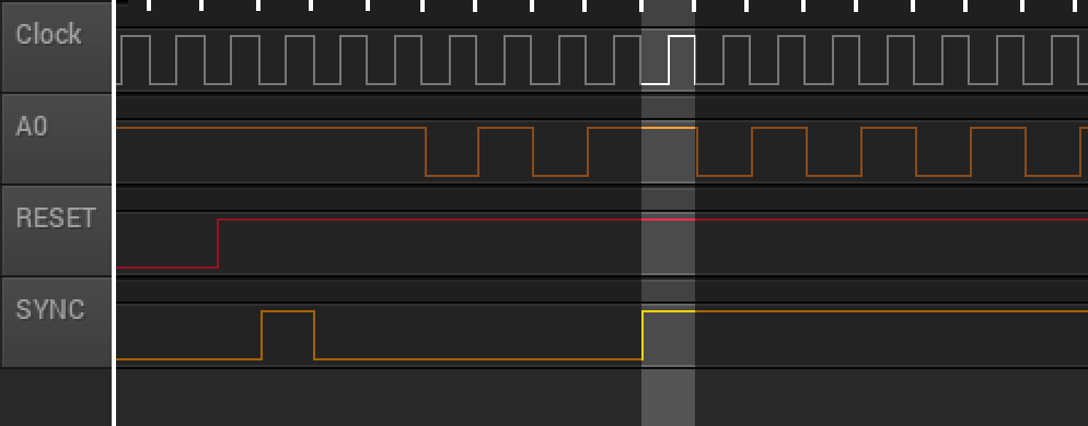
Well look at the behavior I got now. After the RESET, the A0 is down. Does SYNC give a pulse to search for the correct OPCode? I divided the image into 4 "moments" of time that I called t1, t2, t3 and t4. My doubts are:
Databus: $ EAEA
1) What actually happens in t2?
2) Apparently everything is correct at the right time t3?
3) It seemed all correct until t4. What could have happened?
Thank you!
Re: Writing in EEPROM and reading by 6502
Posted: Wed Dec 19, 2018 12:50 pm
by BigEd
Not at all. This is interesting.
T2 is normal: you see the sync pulse during T1, that's the machine doing a RESET by executing something which works like a BRK, a 7 cycle operation.
At T4 the machine seems to switch from 2-cycle instructions (like NOP) to a repeating pattern of 6 cycles. I'm not sure why it might switch, if the databus is hardwired. Could there be an interrupt? Have you tied off NMI and IRQ to low? (I'd be happier if the repeat was a 7 cycle repeat - perhaps it is, and I've miscounted.)
You might find this interesting, or you might find it's a deeper dive than you want right now:
https://www.pagetable.com/?p=410
Re: Writing in EEPROM and reading by 6502
Posted: Wed Dec 19, 2018 7:41 pm
by hitlp
Not at all. This is interesting.
At T4 the machine seems to switch from 2-cycle instructions (like NOP) to a repeating pattern of 6 cycles. I'm not sure why it might switch, if the databus is hardwired. Could there be an interrupt? Have you tied off NMI and IRQ to low? (I'd be happier if the repeat was a 7 cycle repeat - perhaps it is, and I've miscounted.)
No. The data bus is turned on harwired with $ EA. NMI and IRQ are always high. So I do not know why he changes behavior without some change happening.
Anyway I will do all the tests possible. I'm finding that my breadboard is causing all these problems.

Re: Writing in EEPROM and reading by 6502
Posted: Wed Dec 19, 2018 7:50 pm
by BigEd
This sort of thing is always a matter of deduction, and often about figuring out what assumption is wrong.
I see now that the post-T4 behaviour is a pair of 6 cycle instructions - probably the databus value has changed, somehow. If the breadboard construction is noisy or connections are unreliable then the circuit isn't even a constant. That would probably be my top hypothesis.