Page 3 of 4
Re: 4MB SRAM Module
Posted: Thu May 10, 2012 7:44 pm
by GARTHWILSON
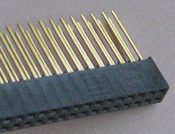
I just ordered some wire-wrap sockets, so now I can provide those as well as soldertail. I'll post a photo of one after they arrive.
Here it is:
Re: 4MB SRAM Module
Posted: Wed Nov 21, 2012 9:20 pm
by BigDumbDinosaur
I'm bumping this topic so it doesn't fade away to page 2.
I recently purchased a 4 MB DIMM from Garth for evaluation purposes. The plan is to use it in POC V2 in lieu of discrete SRAMs soldered to the mainboard. However, curiosity about the use of the MUXed A16-A23 address bits of the 65C816, as well as the desire to investigate the bus drive requirements involved in using a full complement of DIMMs (four for a 16 MB system), is causing me to mull the idea of building a POC "V1-1/2" to play with the DIMM. POC "V1-1/2" would continue to use discrete logic, which is 74AC in POC V1.1 (the current version). I'd switch to 74ABT silicon in SOIC packages to conserve PCB real estate and reduce propagation time, but would otherwise use the same circuit as before.
An alternative would be to include the hardware needed to latch the A16-A23 address bits, which would give the MPU access to the entire DIMM. This entails the use of a bus transceiver for D0-D7, drivers for A0-A15 and a latch for A16-A23. Also, decoding logic would be required to translate A16-A23 into one of 8 chip selects for the DIMM. The transceiver, driver and latch choices are straightforward.
At first blush, it would seem a 74xx138 decoder would be the choice for generating chip selects. I could use a 74AC138 or a 74F138, the latter being slightly faster. However, the decoder's prop time, when added to the prop time of the A16-A23 latch, would consume about 60 percent of Ø2 low at 20 MHz. As the A16-A23 bits are valid only when Ø2 is low and don't become valid until about 40 percent of the way through Ø2 low, that leaves scant time to get a valid address on the bus and have the SRAM respond before the rise of Ø2. Hmm...
Re: 4MB SRAM Module
Posted: Thu Nov 22, 2012 12:00 am
by Dr Jefyll
the decoder's prop time, when added to the prop time of the A16-A23 latch, would consume about 60 percent of Ø2 low at 20 MHz
Just a reminder that you have the option of using a single IC containing both the latch function and the decode function. As you know, this has potential to be faster than two separate IC's (a latch and a decoder) connected externally. Of course you'd have to check the numbers to confirm any particular case.
Two generic latch-decoders I can think of are the 74137 and the 4514. Hitachi seems to offer a 74AC4514, and as for 74AC or 74ACT137, they may be available somewhere also. I guess you could check for both devices in other families as well, such as 74F, 74BCT etc.
cheers
Jeff
ps- you'll still need an IC to latch the high address lines which aren't involved in decoding. But at least the goal of improving your timing margins is achieved.
Re: 4MB SRAM Module
Posted: Thu Nov 22, 2012 7:18 am
by BigDumbDinosaur
Two generic latch-decoders I can think of are the 74137 and the 4514. Hitachi seems to offer a 74AC4514, and as for 74AC or 74ACT137, they may be available somewhere also. I guess you could check for both devices in other families as well, such as 74F, 74BCT etc.
It didn't take me long to shelve this idea. I'll just integrate the DIMM into POC V2 and with a CPLD for glue logic, avoid the timing hassles.
Re: 4MB SRAM Module
Posted: Sat Nov 24, 2012 4:48 pm
by BigDumbDinosaur
Incidentally, for those who are interested in Garth's DIMM and use Express PCB for schematic and board layout, I furnished Garth with an EPCB-compatible schematic component to add to your library. I should have the PCB component available soon. An image of what the schematic component looks like in EPCB is below.
- Wilson Mines 4Mb x 8 DIMM
- dimm_4Mb_x_8_wilson_mines.gif (10.37 KiB) Viewed 4708 times
Re: 4MB SRAM Module
Posted: Sat Dec 01, 2012 6:57 am
by BigDumbDinosaur
Incidentally, for those who are interested in Garth's DIMM and use Express PCB for schematic and board layout, I furnished Garth with an EPCB-compatible schematic component to add to your library. I should have the PCB component available soon. An image of what the schematic component looks like in EPCB is below.
- dimm_schematic.gif (11.46 KiB) Viewed 4674 times
I've also generated a matching PCB component file, which appears in EPCB as follows:
- dimm_pcb.gif (9.63 KiB) Viewed 4674 times
The component layout accounts for the off-center nature of the DIMM when plugged into the socket—I carefully measured the assembly with calipers to get the exact dimensions. Keep in mind, however, that due to the pin layout, the DIMM may be plugged in with the opposite orientation without loss of function.
Here's a ZIP file containing both schematic and PCB component files, which should be copied to wherever your EPCB custom components are located on your system. You can also get this ZIP file from Garth.
- dimm.zip
- (26.36 KiB) Downloaded 161 times
Re: 4MB SRAM Module
Posted: Sat Dec 01, 2012 4:11 pm
by 8BIT
Excellent work! Thanks for the contribution BDD!

Re: 4MB SRAM Module
Posted: Sun Dec 02, 2012 3:38 pm
by BigDumbDinosaur
Excellent work! Thanks for the contribution BDD!
You're welcome.
Incidentally, Garth's DIMM uses the Cypress CY7C1049D SRAM, which has a tpower specification of 100 μs. tpower is the minimum amount of time that must elapse after Vcc has been applied and is stable before reliable access can be made. All SRAMs have this spec, although it's not published in every case. Your reset circuitry should hold /RESET down for at least 5 times that period to avoid an error on first access. Longer tends to be better, especially with some I/O chips that have relatively complicated reset sequences (the 53C94 SCSI controller in my POC unit is an example). I used the Dallas (Maxim) DS1813 reset generator, which has a 250 ms delay from when Vcc stabilizes until /RESET is released.
Also note that like all SRAMs, the cells will initially contain random values, depending on which way the individual flip-flops flopped at power-on. On my POC unit (which uses a smaller 128KB x 8 SRAM), using the D (disassemble) command on an arbitrary range of memory produces what appears to be valid machine code (the 65C816 has no invalid opcodes). It's all garbage, of course.
Re: 4MB SRAM Module
Posted: Sun Dec 02, 2012 3:58 pm
by GARTHWILSON
Also note that like all SRAMs, the cells will initially contain random values, depending on which way the individual flip-flops flopped at power-on. On my POC unit (which uses a smaller 128KB x 8 SRAM), using the D (disassemble) command on an arbitrary range of memory produces what appears to be valid machine code (the 65C816 has no invalid opcodes). It's all garbage, of course.
Re: 4MB SRAM Module
Posted: Sun Dec 02, 2012 9:17 pm
by Dr Jefyll
it will be rather consistent
I've noticed that, too. The RAM contents on power-up will be fairly consistent, though not necessarily 100%.
I'm reminded of an experience from many years ago regarding a hardware/software package I was developing. Briefly stated, I had kind of outsmarted myself with some of the coding, and had unwittingly created a situation in which program behavior was reliant on a certain byte of RAM that never got initialized.

Due to the semi-consistency of the RAM's power-up data, I ended up with a bug that manifested itself only rarely -- a very nasty problem to deal with! Unfortunately the situation went from bad to worse.
As we know, intermittent symptoms usually indicate flaky connections or electrical noise. So I started making changes to the hardware -- I forget the exact details -- and, sure enough, I observed a difference in how often the bug would appear. Maybe I'd inadvertently changed the rate at which the +5 ramps up upon power-on -- could that affect the RAM's initial contents? I don't know, but one thing for sure is that I was wasting my time barking up the wrong tree. Although hardware
seemed to play a role, in fact the trouble was strictly a software issue.
The hours I spent unraveling the puzzle were not happy ones; I was pulling all-nighters trying to prepare a demo for the client. I don't recall ever having a bug that caused me more grief.
True stories from the trenches!

-- Jeff
Re: 4MB SRAM Module
Posted: Sun Dec 02, 2012 10:02 pm
by BigDumbDinosaur
it will be rather consistent
I've noticed that, too. The RAM contents on power-up will be fairly consistent, though not necessarily 100%.
I got curious about this a while back and decided to note the random values in eight contiguous POC memory locations at power-up. If POC had been powered off for a while the eight locations would consistently come up with the same "random" values. However, if I let the unit run for a while, shut it down long enough to assure that Vcc was at zero (e.g., 10 seconds) and then power it again, those locations would contain different "random values." I surmised that the SRAM's die temperature was the likely cause of the difference.
Re: 4MB SRAM Module
Posted: Sun Dec 02, 2012 11:09 pm
by Dr Jefyll
I surmised that the SRAM's die temperature was the likely cause of the difference.
Hmmm, good call -- that seems plausible. And, besides voltage and temperature, probably there are additional factors as well.
Thinking out loud: a SRAM cell is a symmetrical circuit, and theoretically the two halves of the cell should behave identically. If reality matches the theory, that means the cell would power up in a meta-stable condition (both sides in the linear region between 0 and 1) and would remain balanced on the razor's edge until something (thermal noise? the gradient of a stray electrostatic field?) infinitesimally tipped the scales -- after which the change would snowball, with one half going to 0 and the other half to 1.
the Cypress CY7C1049D SRAM [has] a tpower specification of 100 μs. tpower is the minimum amount of time that must elapse after Vcc has been applied and is stable before reliable access can be made.
When I read this it left me wondering, as I don't suppose a SRAM chip would have a charge pump/bias generator that needed to build up a head of steam. But could the tpower spec be intended to allow time for meta-stability to resolve? (Both explanations strike me as unlikely!)
-- Jeff
Re: 4MB SRAM Module
Posted: Mon Dec 03, 2012 1:15 am
by Dajgoro
What are you trying to achieve with uninitialized ram? A random generator?
Re: 4MB SRAM Module
Posted: Mon Dec 03, 2012 6:22 am
by Arlet
I've used the contents of uninitialized memory as a seed of a random generator before. This can be useful for instance to help generate unique IDs in an ad-hoc network situation.
Re: 4MB SRAM Module
Posted: Mon Dec 03, 2012 6:32 am
by Dajgoro
Speaking of random generators, i built one of 4000 series cmos ic, as part of a collage project, i plan to add a bus interface, so i can use it in my sbc.
BigEd gave me a link(I can't find it anymore) about Intels new random generator that utilizes a bistable for generating random values.
As for the ram modules, i think i am going to get them for my MC68020 sbc project.