Page 19 of 29
Re: 65XX SBC general help and color display help needed
Posted: Wed Feb 06, 2019 4:23 am
by backspace119
So I finished wiring up the new layout, there are a few weird spots, but the processor busses (for the most part) are pretty straight and clean. Here's a picture:
and the 3d view to go with it (note, the MAX232 caps still aren't changed to ceramics yet, because I didn't source the parts yet)
Re: 65XX SBC general help and color display help needed
Posted: Thu Feb 07, 2019 6:13 am
by backspace119
Alright so, I've been very busy with work the past few days and haven't had a lot of time to put into this, but I just cleaned up the board a bit and ran it through DRC and fixed a few errors. I'm going to source the replacement capacitors, then I think it should be pretty much done.
Before I send this off somewhere to have it made, has anyone spotted any potential issues? I'm going to try and hit max speed on this, at 16Mhz, but if I can only do 5-10 that's fine too, if I need to upload more docs/detail/pictures I can, I just really want this to work on the first try.
Re: 65XX SBC general help and color display help needed
Posted: Fri Feb 08, 2019 12:15 am
by backspace119
As I've been sourcing the logic components, I noticed that the F series of 74xx components tend to be pretty fast, and cheap. It didn't strike me as odd until I noticed "bipolar" as the technology on one of their datasheets. After doing a bit of research, it appears that the F series is the fast bipolar series, it's not in the CMOS series. I'm thinking that I may have to look for AC or similar, which are quite a bit more expensive, but will the F series work at all?
I'm thinking here it may be like what garth was talking about earlier, that the logic 1 for these devices may not be at a CMOS compatible level.
Also, I re-read the post that Garth links to in the primer on good AC circuit design, but this time I went back earlier in the same thread and read the posts by BDD and the op of that thread. The op linked to some application notes from Altera that had some info in them for board design. One of the things mentioned was to keep the clock trace as straight as possible, with as few vias as possible (preferably none) and about equidistant to all the devices its feeding (to prevent out of phase operation).
In mine, you'll see I shoved the oscillator + flip flop right beside the 65816, then routed it to the other devices that needed it (using about 4 vias in total to get it around the board). Should I go back and redo this to move the clock to a more central location? Or will it not matter at these speeds?
Re: 65XX SBC general help and color display help needed
Posted: Fri Feb 08, 2019 1:01 am
by GARTHWILSON
In mine, you'll see I shoved the oscillator + flip flop right beside the 65816, then routed it to the other devices that needed it (using about 4 vias in total to get it around the board). Should I go back and redo this to move the clock to a more central location? Or will it not matter at these speeds?
Phase propagation velocity on FR-4 PCB is seven or eight inches per nanosecond (I don't remember exactly). One inch's difference in length is not going to make any significant difference for
timing skew with the circuit components you're using.
As for vias, they will offer a little discontinuity in the transmission-line impedance, primarily from their inductance since yours are so tiny; but you are not controlling the impedance anyway. Your combination of board size and edge rates have not solidly crossed into an area where you really need to. (I would comment here also that terminations have little effect if they're nowhere close to the characteristic impedance of transmission lines.)
There are ways to make corners behave well even with very fast edge rates, but again, I don't think it's a concern with the stuff we're working with. The primary concern with the fastest of our stuff, and boards your size and smaller, is just to have a continuous ground plane and good bypassing.
At our speeds, it seems like 80% or 90% of projects work in spite of poor AC design; but occasionally we have a forum member who has problems with his creation that are almost impossible to figure out, and it's pretty clear to me that it's because of the construction methods. (These are usually solderless breadboards.) If I can keep helping people understand what's going on there, I will be glad to get the success rate up to 100%, rather than settling for 80% or 90%.
Re: 65XX SBC general help and color display help needed
Posted: Fri Feb 08, 2019 1:07 am
by backspace119
In mine, you'll see I shoved the oscillator + flip flop right beside the 65816, then routed it to the other devices that needed it (using about 4 vias in total to get it around the board). Should I go back and redo this to move the clock to a more central location? Or will it not matter at these speeds?
Phase propagation velocity on FR-4 PCB is seven or eight inches per nanosecond (I don't remember exactly). One inch's difference in length is not going to make any significant difference for
timing skew with the circuit components you're using.
As for vias, they will offer a little discontinuity in the transmission-line impedance, primarily from their inductance since yours are so tiny; but you are not controlling the impedance anyway. Your combination of board size and edge rates have not solidly crossed into an area where you really need to. (I would comment here also that terminations have little effect if they're nowhere close to the characteristic impedance of transmission lines.)
There are ways to make corners behave well even with very fast edge rates, but again, I don't think it's a concern with the stuff we're working with. The primary concern with the fastest of our stuff, and boards your size and smaller, is just to have a continuous ground plane and good bypassing.
At our speeds, it seems like 80% or 90% of projects work in spite of poor AC design; but occasionally we have a forum member who has problems with his creation that are almost impossible to figure out, and it's pretty clear to me that it's because of the construction methods. (These are usually solderless breadboards.) If I can keep helping people understand what's going on there, I will be glad to get the success rate up to 100%, rather than settling for 80% or 90%.
Thanks for all this, this is very encouraging. One thing I forgot to mention in my last post, is the Ap. note also says to stay away from sockets. I know I'm using a socket for the eeprom, no matter what, but should I really stay away from sockets for other components? I was going to socket as much as I could for easy replacement/testing new parts.
I may try and do a little bit of cleanup (get some vias out, take some of the particularly bad lines and try and make them straighter) but from what you're saying it sounds like most likely I won't run into issues, since I have internal GND and VCC planes that are contiguous anyway.
Re: 65XX SBC general help and color display help needed
Posted: Fri Feb 08, 2019 1:17 am
by GARTHWILSON
I think sockets can be rather benign at our speeds. Humph—For that matter, if they let you put parts under ICs, they could help reduce the board size, which would be helpful anyway.

It's a bit scary to think of the possibility of needing to remove or replace an IC that's not socketed.
Re: 65XX SBC general help and color display help needed
Posted: Fri Feb 08, 2019 1:29 am
by backspace119
I think sockets can be rather benign at our speeds. Humph—For that matter, if they let you put parts under ICs, they could help reduce the board size, which would be helpful anyway.
It's a bit scary to think of the possibility of needing to remove or replace an IC that's not socketed.
It is, I've done it before, but it took a hot air kit, about 2 hours, and a lot of patience (and it was only dip-14 iirc). So then sockets it is, although I don't have a lot of components to hide under the ICs (I have a lot of caps, but looking at them I don't think they'll fit under the chip, I could shove the resistors underneath, but there's only a couple on the board.
Re: 65XX SBC general help and color display help needed
Posted: Fri Feb 08, 2019 1:34 am
by backspace119
I also just realized that my clocks I have dip 14 sockets for, I can probably put those on dip-8 and save a bit of space
Re: 65XX SBC general help and color display help needed
Posted: Fri Feb 08, 2019 1:38 am
by GARTHWILSON
What I have done many times when the IC was not worth endangering the board was to cut all the leads of the IC and remove them one by one. This was with our analog circuits that have a lot of op amps for example which cost us around twenty cents each, on a multilayer board with hundreds of parts on it.
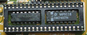
As for parts under parts, I was thinking of this kind of thing:

(This is from the "
Getting More on a Board" section of the 6502 primer.) I took this picture from an old PC motherboard I had here.
Re: 65XX SBC general help and color display help needed
Posted: Fri Feb 08, 2019 2:15 am
by backspace119
What I have done many times when the IC was not worth endangering the board was to cut all the leads of the IC and remove them one by one. This was with our analog circuits that have a lot of op amps for example which cost us around twenty cents each, on a multilayer board with hundreds of parts on it.
As for parts under parts, I was thinking of this kind of thing:
(This is from the "
Getting More on a Board" section of the 6502 primer.) I took this picture from an old PC motherboard I had here.
I remember that picture now, I swear, every time you put something here from the primer it's always the part that I've forgotten. I remembered the picture where you had staggered resistors and diodes, but not this one. This may not be a half bad idea for the memory/address bus demultiplexing system, since the BAD lines (my net names for the multiplexed side) only need to connect to those chips, and then the address and data lines can come out between the pins.
The smaller I make this, the cheaper it gets, and potentially the better performance since I'll have shorter traces, so I think it's worth it going over this again and again, redoing the work until its right.
Also, the manufacturer I'm looking at, Seeed Studio, is observing the chinese lunar new year, and won't open back up till the 11th I think, so I have some time to spare.
Re: 65XX SBC general help and color display help needed
Posted: Fri Feb 08, 2019 3:52 am
by Dr Jefyll
The smaller I make this, the cheaper it gets
 Viewed 763 times")
- ANIMATION
Can you do this? And there are other opportunities. As you say, it's worth going over it again. Really, there's quite a lot of unpopulated area.
Have fun!

Re: 65XX SBC general help and color display help needed
Posted: Fri Feb 08, 2019 4:51 am
by Arlet
It is, I've done it before, but it took a hot air kit, about 2 hours, and a lot of patience (and it was only dip-14 iirc).
It can be done in 5 minutes with some wire cutters
Re: 65XX SBC general help and color display help needed
Posted: Fri Feb 08, 2019 6:33 am
by Chromatix
About 74F series logic: it's pretty fast, yes, but it's *very* power hungry, on the order of 35mW per simple logic chip. It has typical TTL input levels, input loads (this is *not* a high-impedance input, due to the bipolar transistors involved) and fanout restrictions. It's also no longer being manufactured.
If you need fast logic, I recommend 74AHC series, switching to 74AC or 74HC for specific devices not available in that series. A quick pricing comparison suggests there's not much difference.
Re: 65XX SBC general help and color display help needed
Posted: Fri Feb 08, 2019 6:41 am
by backspace119
The smaller I make this, the cheaper it gets
Animation1.gif
Can you do this? And there are other opportunities. As you say, it's worth going over it again. Really, there's quite a lot of unpopulated area.
Have fun!
That's an amazing idea right there, I've been spending time cleaning up some bad traces, got the via count down from ~750 to ~650, moving those might help some too (although might put some feet over vias, but who cares, needs re routing anyway). This, combined with making the clocks smaller (dip 8 instead of dip 14) I can probably save some good board space.
I may go with what Garth was suggesting and throw some chips underneath the bigger chips sockets, although that would mean not putting the smaller chips in sockets (unless they were really short). Honestly, that will be a last resort.
I don't remember if I mentioned this, but OSHPark (I've gotten boards from them before, and they're good quality) quoted me about $420 to make this. That's for 3 boards, but that's still over $100 a board! Seeed I have not actually done a quote with (haven't uploaded the file) but they have a configurator where you can put in all the specs for your board, and they were quoting me about $150 for 10 boards!
I don't think OSHPark's quality is worth paying nearly 10x as much per board, and the turn around times (minus the fact that seeed is closed due to the chinese lunar new year until the 11th) are about the same from what I've seen. Plus, OSHPark only sells purple boards, and for this project, I'd like the "old fashioned" green a lot more. (seed even lets you get them in other colors, like black, blue, etc).
OSHPark, and some other american board makers with them, are good companies, but they probably need to refine their process to be able to compete with places like Seeed, because I don't see the point in paying all that extra money.
About 74F series logic: it's pretty fast, yes, but it's *very* power hungry, on the order of 35mW per simple logic chip. It has typical TTL input levels, input loads (this is *not* a high-impedance input, due to the bipolar transistors involved) and fanout restrictions. It's also no longer being manufactured.
If you need fast logic, I recommend 74AHC series, switching to 74AC or 74HC for specific devices not available in that series. A quick pricing comparison suggests there's not much difference.
I only remember seeing the price difference on one chip, the 74318, and the AC (maybe AHC, pretty sure it was AC though) version was >$2, while the F was $0.60. For a chip that I need 3 of, the cheaper option (that was basically as fast) looked better, but knowing this, I'll stay far away from the F series.
Re: 65XX SBC general help and color display help needed
Posted: Fri Feb 08, 2019 6:50 am
by backspace119
The smaller I make this, the cheaper it gets
Animation1.gif
Can you do this? And there are other opportunities. As you say, it's worth going over it again. Really, there's quite a lot of unpopulated area.
Have fun!
Thanks again for this, I just made the move and it saved me about 20mm on the y axis. That's about $20 saved right there on having it manufactured. I'm going to keep looking around and see if there's other stuff I can push closer together, now that I've broken some tracks, I'm a lot less hesitant to shuffle things around again.