Page 16 of 18
Re: Blue April - RC6502 Project Space
Posted: Wed Mar 22, 2023 1:55 am
by GARTHWILSON
Nice! And so modern (compared to the kerosene lamp in the window sill  )!
)!
Re: Blue April - RC6502 Project Space
Posted: Wed Mar 22, 2023 10:28 am
by sburrow
That was neat to see! Great job, very cool to watch it in action. I like how you have the ability to just turn ports on and off from the monitor, and even seeing that the timers are counting like that is pretty cool. I cannot do any of that from my monitor at the moment, so I'm a bit jealous

I know that you have plans to run video from PB-1 (or using PB-1?), would that eventually connect to Blue April? As a retrospective, do you find the modular design with the backplane easier or better overall? I don't think PB-1 does that, it's a more singular unit, right? Are you going to do a video on PB-1 sometime?
Thanks for the video!

Chad
Re: Blue April - RC6502 Project Space
Posted: Wed Mar 22, 2023 3:45 pm
by Paganini
Hi Chad,
Those are some good questions! I think anything that I make for PB-1 will be pretty easy to move over to Blue April; conceptually they're very similar: 64k split into 32k (top) for ROM and 32k (bottom) for RAM with a jumper configurable I/O window stealing some bytes from one or the other. (In the case of PB-1, DIP switch configurable!
) PB-1 doesn't have a backplane but it does have a big edge connector and all of the individual pins of the ICs are accessible so it's easy to connect things to it. (That was the main point of building it.
)
I would have to say that I'm ready to move on from backplanes. The advantage of backplanes from a learning standpoint is that they shrink the practice space. The schematic for each module is small and manageable, so that I could make sure I understood exactly what every connection was for and what every component did before I started soldering. It also made debugging easier in some ways, in that I could, e.g., just plug the CPU module into a breadboard and follow along with a Ben Eater video. If something went wrong after that I could be pretty confident the CPU module wasn't at fault.
Now, though, I find the backplane cumbersome. It takes up much more space than it needs - *all* of PB-1 fits onto a card just slightly wider than one of Blue April's modules. CPU, RAM, ROM, and Clock / Reset take up *four* backplane slots without giving you all that much flexibility in return. Additionally, unlike Acolyte with its nifty prototyping / bodge area, it's practically impossible to change any of the modules after the fact. There's just nowhere to put diodes or an AND gate to allow the use of multiple WDC 65c22s, for example.
If I was going to make a 3rd design, I think I'd want it to be something like the
Planck: an SBC with an expansion bus. In fact, I think the guy who designed the Planck did so after similar experience with the RC6502.
A video on PB-1 would be kind of boring right now, I think - not much to show! Maybe after I get VGA working on it would be a good time for a video tour.
Re: Blue April - RC6502 Project Space
Posted: Sat Jul 08, 2023 4:30 pm
by Paganini
NRRRRYYYRGH
Posted: Wed Jul 12, 2023 4:59 pm
by Paganini
This is not exactly on topic, but...
I'm out of town for a couple of weeks to play a show, so I thought this might be a good time to learn how to make schematics with KiCAD. I can see it is a powerful tool. Alas, the UI is frustratingly bad, at least the MacOS version. (When I say "UI" I mean things like having sane default behavior for basic stuff, like what happens when you click a button, zooming / scrolling with the touchpad, and so on.)
I'm trying to connect a data bus between a 6502, SRAM, and flash ROM. There are a couple of youtube tutorials for this that I've found, so I've gotten to the point where I can actually make the bus. However. Once you give labels to all the pins that are supposed to connect to the bus, you have to give a label to the bus itself so that it knows those pins are its members. There's a little "create label" tool that looks like an A with a line under it. When you use that tool, you get a label that looks like this:
The little box in the lower left is how you connect the label to the bus (the blue line). I can't for the life of me figure out how to change the location of the actual text in relation to that box. The default arrangement makes it so that the label OVERLAPS the bus line. I want to move the label text further away from the bus line, and also I want to move it UNDERNEATH the bus line. Is there a way to do this? I may delete KiCAD in a fit of rage...
Re: NRRRRYYYRGH
Posted: Wed Jul 12, 2023 5:46 pm
by gfoot
I'm out of town for a couple of weeks to play a show, so I thought this might be a good time to learn how to make schematics with KiCAD. I can see it is a powerful tool. Alas, the UI is frustratingly bad, at least the MacOS version. (When I say "UI" I mean things like having sane default behavior for basic stuff, like what happens when you click a button, zooming / scrolling with the touchpad, and so on.)
It's a funny UI for sure, and nobody would accuse it of being intuitive - but in some respects it's quite efficient as a lot of things are keyboard-driven.
The v7 release unified things a little bit between the schematic editor and PCB editor (which are quite separate programs, hence the discrepancies) but it still feels much the same to me, i.e. fine as I'm used to it but surely quite hard for newcomers!
I'm trying to connect a data bus between a 6502, SRAM, and flash ROM. There are a couple of youtube tutorials for this that I've found, so I've gotten to the point where I can actually make the bus. However. Once you give labels to all the pins that are supposed to connect to the bus, you have to give a label to the bus itself so that it knows those pins are its members. There's a little "create label" tool that looks like an A with a line under it. When you use that tool, you get a label that looks like this:
Screen Shot 2023-07-12 at 12.33.51 PM.png
The little box in the lower left is how you connect the label to the bus (the blue line). I can't for the life of me figure out how to change the location of the actual text in relation to that box. The default arrangement makes it so that the label OVERLAPS the bus line. I want to move the label text further away from the bus line, and also I want to move it UNDERNEATH the bus line. Is there a way to do this? I may delete KiCAD in a fit of rage...
R will "rotate" things and it changes the location of the text with respect to the anchor, but not a great deal. I think the anchor will always be under the text for horizontal text but you can make it be on the left or the right. I haven't noticed it overlapping bus lines before, but can't be sure that it doesn't. Maybe there are some global settings somewhere that you could change to move labels further from their anchors - or you could position it where you did and draw a little extra bus line from the anchor to the bus.
Also to some extent the bus label is not super important - the matching labels at the end of the bus actually link the pins even if you don't draw the bus line in, or don't label it! Correctly named buses are important for cross-sheet links though. The modern KiCad actually has better support for these things than the old one, I think you can more centrally define the buses as well instead of it being so dependent on the label like that.
Re: Blue April - RC6502 Project Space
Posted: Wed Jul 12, 2023 5:50 pm
by Proxy
Eh you just kinda get used to KiCad's jank after some time.
I can't count the amount of times I have encountered missing functionality for things I would consider pretty basic, only to forget about it a while later because I wanted to get finished with the schematic/PCB and can't waste time being mad.
Looking at my own SBC's Schematic, I simply placed the bus label directly on the line. it's still fully readable so it didn't really bother me.
If you do care about the aesthetics of the schematic then you could try something like this:
or maybe sideways.
or be like me and just go "screw it, it's readable"
(note that i reduced the text size to 1.0, though even default work without poking out the bottom)
Re: Blue April - RC6502 Project Space
Posted: Wed Jul 12, 2023 6:32 pm
by Paganini
Hehe. Thanks guys.
The v7 release unified things a little bit between the schematic editor and PCB editor (which are quite separate programs, hence the discrepancies) but it still feels much the same to me, i.e. fine as I'm used to it but surely quite hard for newcomers!
Interesting, I didn't know there was a v7. Mine is v6; I installed it last month, but only just now got around to trying to figure it out. Did v7 come out recently, or is the MacOS version just lagging?
Eh you just kinda get used to KiCad's jank after some time.
I can't count the amount of times I have encountered missing functionality for things I would consider pretty basic, only to forget about it a while later because I wanted to get finished with the schematic/PCB and can't waste time being mad.
Yes, my experience today has been basically just like that, alternating between "WTF I COULD DO THIS IN 1998 WITH MICROSOFT PUBLISHER THERE IS NO EXCUSE FOR THIS NONSENSE" and "...OK fine, whatever, moving on." You could use me as a clock oscillator.
I will take your suggestion to give the labels their own little attachment points at the end of the bus and let my blood pressure settle down.
Re: Blue April - RC6502 Project Space
Posted: Wed Jul 12, 2023 6:59 pm
by gfoot
I didn't know there was a v7. Mine is v6; I installed it last month, but only just now got around to trying to figure it out. Did v7 come out recently, or is the MacOS version just lagging?
I think it was released at the start of the year., I'd hope the mac version was released too.
Re: Blue April - RC6502 Project Space
Posted: Wed Jul 12, 2023 11:23 pm
by Paganini
I think I'm getting the hang of this.
Re: Blue April - RC6502 Project Space
Posted: Wed Jul 12, 2023 11:47 pm
by gfoot
Nice. I would flip RN201 so that the "+5V" comes out at the top but it's not a big deal. There is a problem though as all the "P" inputs to U203 are shorted to ground...
Re: Blue April - RC6502 Project Space
Posted: Thu Jul 13, 2023 3:33 am
by Paganini
Nice. I would flip RN201 so that the "+5V" comes out at the top but it's not a big deal.
Good idea! Done!
There is a problem though as all the "P" inputs to U203 are shorted to ground...
LOL, I just noticed that. I also swapped the resistor network and the DIP switches! Here's what it's supposed to look like:
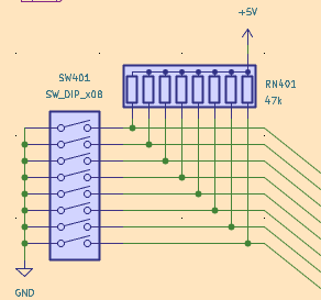
- Screen Shot 2023-07-12 at 11.31.37 PM.png (14.91 KiB) Viewed 1131 times
Re: Blue April - RC6502 Project Space
Posted: Thu Jul 13, 2023 2:33 pm
by sburrow
I've been using KiCad for a while now. I remember before having found it, I was trying a variety of Linux-based solutions, and none of them were even close to the power of KiCad. It might have a few weird things here and there, but it is far better than many alternatives, especially in Linux-land.
So what are you working on specifically? I see your "Glue" picture, but what is the goal here eventually?
A good use of time!
Chad
More fun with KiCAD
Posted: Thu Jul 13, 2023 5:12 pm
by Paganini
So what are you working on specifically? I see your "Glue" picture, but what is the goal here eventually?
I'm working on a full schematic for my next project. It will be a more full-featured "home computer" style build pulling together what I've learned so far from previous projects, and expanding a bit. (It will have some basic RAM/ROM banking, which I haven't done before, and an ACIA for serial connections.)
Here's today's KiCAD headscratcher. I wired up the CPU, RAM, and ROM like this:
I created global labels A[0..15] and D[0..7] for the address and data buses, then unfolded the connections for each line where it connects to the various ICs, just like you see in the picture. When I run the error check, there's no complaints on this sheet. Over on the I/O sheet I wired up the VIAs like this:
You can see I created the same data bus, then broke out its individual lines. I also broke out individual address lines to connect them to the VIAs' register select lines. Again, no problems. On that same page I also broke out D0 to create an output "register" to control RAM/ROM banking:
That also worked OK! So the concept I'm working from is that creating a bus with the X[Na..Na+z] syntax creates all the individual labels (Na, Na+1, Na+2, etc.) and makes them available for individual connections. However, over on the glue logic sheet, where I did exactly the same thing for the address bus, I get a bunch of errors saying "label A4 is not connected to anything," "label A5 is not connected to anything," etc., for every address label that I fanned out from the address bus.
I'm stumped!
Re: Blue April - RC6502 Project Space
Posted: Thu Jul 13, 2023 5:32 pm
by Proxy
hmm, only difference i can see is that on the second image, you have the Data bus defined twice, once locally (next to U505) and once globally.
while with the address bus in the last image, you only use the global label.
so to me that seems like the global labels aren't actually working and the only reason the data bus one didn't throw an error is because of the local label attatched to the same bus.