Page 16 of 18
Re: 28Cxxx EEPROM Programmer
Posted: Sat Jul 15, 2017 11:03 pm
by theodor613
Thanks BigEd, now i know.
Dwight, You would have to download the eagle schematic on page 8, my apology for not clarifying that. But yes, I am using an Arduino Leonardo as the programmer was designed to run on an Arduino Uno/Leonardo. I have already programmed the board to run a rgb led and it runs fine. As soon as i have time, i will solder a new board and make sure the 12v pump circuit works as intended. Right now it is dropping to 0v when i try to erase the chip.
Re: 28Cxxx EEPROM Programmer
Posted: Sun Jul 16, 2017 12:00 am
by dwight
Is that with or without a chip in the socket?
I don't read Eagle schematics that I know of.
I'm typing from a Chrome book. I don't think I can
ungzip or digest a tar file.
It would be niece if you could post a pdf of the schematic.
Please don't post as links, they get lost.
Dwight
Re: 28Cxxx EEPROM Programmer
Posted: Sun Jul 16, 2017 12:09 am
by Michael
I, for one, would be extremely grateful if someone could post that schematic as a JPG, PNG, or PDF...
Cheerful regards, Mike
Re: 28Cxxx EEPROM Programmer
Posted: Sun Jul 16, 2017 1:15 am
by theodor613
This was taken from page 7 I believe. I'm on my phone so I can't undrar/unzip any packages.
viewtopic.php?f=4&t=2491&start=90
Re: 28Cxxx EEPROM Programmer
Posted: Sun Jul 16, 2017 2:21 am
by dwight
What is the frequency and the duty cycle width used for
the 12v boost.
There doesn't look to be any voltage control other than the
duty cycle width. The voltage could go almost any where.
Why doesn't it have a voltage monitor on one of the A/D inputs?
Dwight
Re: 28Cxxx EEPROM Programmer
Posted: Sun Jul 16, 2017 3:06 am
by theodor613
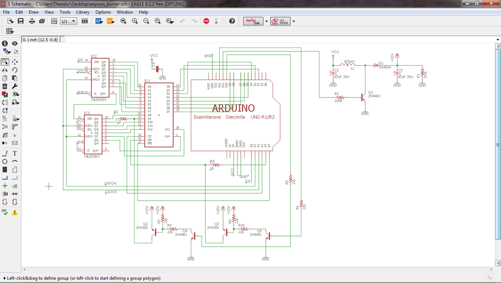
this is the actual circuit. This circuit was not designed by me. so i don't have any answers.
Update: 2 things
1st - A short was found between the R10 solder pads. Scratched off the trace and there's no continuity between the pads. My fault when designing the pcb and i just switched to eagle cad and rushed the pcb design.
2nd - I am now using a DC adapter and the chip will erase. But only if i press the erase button multiple times(5-7 times in a row).
Re: 28Cxxx EEPROM Programmer
Posted: Sun Jul 16, 2017 4:48 am
by dwight
The spec says 100 to 500 ms. I don't think
there is an issue with it being a little longer then that.
A pulse width of 100 ms is easy to check on a scope.
There is a hold delay time that might be violated.
A9 and Vpp must be on and off before CE is changed.
This could easily be violated if they are slow in transition.
Dwight
Re: 28Cxxx EEPROM Programmer
Posted: Tue Jul 18, 2017 12:27 am
by theodor613
remove the boost components on the shield and wired in a dc booster with an enable pin. Still no go.
Re: 28Cxxx EEPROM Programmer
Posted: Tue Jul 18, 2017 1:57 am
by dwight
It is possible that previous attempts with the last boost circuit might have damaged the IC. Are you using a fresh part?
Dwight
Re: 28Cxxx EEPROM Programmer
Posted: Tue Jul 18, 2017 2:12 am
by theodor613
Ic is fine, it reads and write in another programmer just fine. I've been cycling through 5 ic. Going to take a few days break from this. Got a video game console mod that I'm gonna focus on finishing.
Re: 28Cxxx EEPROM Programmer
Posted: Tue Jul 18, 2017 10:19 am
by John West
The short on R10 could have damaged Q3. With no chip in the socket and no Arduino attached, put a ~4K resistor between the emitter of Q3 and ground, then pull the base of Q5 high (through its resistor!) and see what voltage you get.
And that voltage boost circuit is a big worry. There's no regulation, so who knows what voltage it's giving you. The 27SF512 looks relatively fussy about its VPP.
Re: 28Cxxx EEPROM Programmer
Posted: Tue Jul 18, 2017 12:12 pm
by theodor613
The short on R10 could have damaged Q3. With no chip in the socket and no Arduino attached, put a ~4K resistor between the emitter of Q3 and ground, then pull the base of Q5 high (through its resistor!) and see what voltage you get.
And that voltage boost circuit is a big worry. There's no regulation, so who knows what voltage it's giving you. The 27SF512 looks relatively fussy about its VPP.
I already soldered a new board with the short removed. The Same issue was found on the new board.
Yes, the 27sf512 is fussy with VPP, pita.
But with the shield removed, boost circuit removed, regulated dc booster added with r2 soldered to the enable pin and no chip in the socket, I am able to get 12v. But once I placed them in the Arduino, it reads 5v on standby and 0v when reading, erasing or programming.
I'll give it a go with the 4k resistor on Q3 later on as I brought the boards into work with me. Just have to find a 4k resistor. Thanks.
Re: 28Cxxx EEPROM Programmer
Posted: Tue Jul 18, 2017 12:43 pm
by John West
By ~4K I mean 'approximately 4K'. It's just to simulate the 27SF512's worst case VPP load (4K = 12V/3mA). Any value vaguely in that area will do. 4K isn't a standard value. 3.9K is, or if you don't have one of those, 4.7K is common.
Re: 28Cxxx EEPROM Programmer
Posted: Tue Jul 18, 2017 1:05 pm
by theodor613
I figured that wasn't a standard value. I can alway get close to it by putting some resistor in series.
It's amazing what 2 capacitors can do. Got the board to program the 27sf512 successfully.
Re: 28Cxxx EEPROM Programmer
Posted: Sun Jul 23, 2017 1:43 pm
by theodor613
Would it be possible to add the clone arduinos uno and nano? I believe that they are define as usb-serial ch3440.