Joined: Fri Aug 30, 2002 1:09 am
Posts: 8546
Location: Southern California
|
Tip of the day, #32
Many projects seen on 6502.org have wires soldered to solder-tail IC sockets. I like certain solder-type breadboards for analog work with all its discrete components; but digital work is almost all IC's, and wire-wrap generally works much better. The tool, tightly wrapping clean wire onto clean posts, makes the corners of the posts bite into the wire, producing a chemical weld. If you unwrap, you can sometimes feel the microscopic welds breaking. Since you don't need to get a soldering iron in between pins, the IC sockets can go right together with no board space between. The shorter wires improve operation with high-speed parts. In my 20 years of using WW, it has proven to be 100.00% reliable. I use the OK Industries WSU 30-M manual wrap tool (the blue one near the top in the picture below). To avoid wire breakage at the end of the insulation, the WSU 30-M wraps a couple of turns of insulated wire first. This insulated part can go over a previous WW since it doesn't need to touch the actual post. This way, you can always get 3 wraps on a 2-level post. Individual turns of bare wire should go against each other with no space between and no overlapping. Practice makes perfect. Do not solder them!
Attachment:
 OKIndManualWWtools2.jpg [ 44.82 KiB | Viewed 6285 times ]
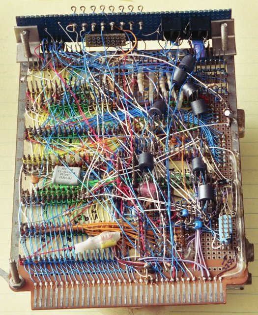
The little blue one near the top is the tool I used to WW my workbench computer whose bottom is shown here:

This 4.5 x 6.5" board has 19 ICs plus connectors, keypad, LEDs, DIP headers for discretes, and the piezoelectric beeper, all of which take room. As you can see, you can put parts shoulder to shoulder with no gaps between them, and in most cases, have the wires straight (meaning as short as possible) and without risk of breakage from movement, unlike the situation with soldering wires. Although I've added to it over the years, I used it regularly since originally making it 28+ years ago (as of the time of this edit, Nov 2021), and never had any trouble with it.
The dark-gray drums are ferrite beads put over twisted pairs of wires to reduce unwanted high-frequency digital common-mode signals, forcing them to be differencial. Six of them are in the analog inputs and outputs for the A/D and D/A converters which are very well behaved as a result, in spite of not having a ground plane.
Wire-wrap questions and doubts are answered at http://wilsonminesco.com/6502primer/WireWrap.html .
_________________ http://WilsonMinesCo.com/ lots of 6502 resources
The "second front page" is http://wilsonminesco.com/links.html .
What's an additional VIA among friends, anyhow?
Last edited by GARTHWILSON on Mon Mar 05, 2012 5:59 am, edited 2 times in total.
|
|


