Page 11 of 41
Re: Concept & Design of 3.3V Parallel 16-bit VGA Boards
Posted: Sun Dec 09, 2012 7:47 pm
by Arlet
Well, the board works again, and it was not the FPGA that was cooked. Instead there was a ~90 Ohm short between the PROGRAM trace and ground, somewhere in the board itself. I removed both PROM ICs, and I lifted the PROGRAM pin on the FPGA, and something was still pulling down the PROGRAM signal. I ended up cutting the trace on the back of the board, near R1, where it goes to the PROMs, and that fixed it.
Re: Concept & Design of 3.3V Parallel 16-bit VGA Boards
Posted: Sun Dec 09, 2012 7:54 pm
by Arlet
Anyway, I
checked in some line drawing experimental code. It's still limited, but seems to work. Only a single line from 0,0 to w,h is supported, and w > h. Also, there's no end condition yet, so the line will continue all the way until the bottom of the screen, wrapping along the X-axis. Part of the code has been copied from my sprite code, and it still contains some references to sprites.
Re: Concept & Design of 3.3V Parallel 16-bit VGA Boards
Posted: Sun Dec 09, 2012 7:59 pm
by ElEctric_EyE
Excellent! I'll re-check the v1.0h design, as I have not tried using it yet, and compare it to my functioning v1.0g board. I really don't remember changing anything related to the JTAG programming, except for the fix to the MUX.
One question though: It was working before, why would it have stopped working all of a sudden?
Haha, you're tackling lines?! Awesome!
Re: Concept & Design of 3.3V Parallel 16-bit VGA Boards
Posted: Sun Dec 09, 2012 8:22 pm
by Arlet
One question though: It was working before, why would it have stopped working all of a sudden?
No idea. I had both PROMs removed, and the FPGA pin lifted, and there was still a connection between ground and the PROGRAM signal. After everything worked, I tried to investigate some more, but then the "short" disappeared.
I looked at the entire length of the trace with a magnifying glass, but couldn't see anything suspicious. One possible explanation is that some flux was left on the board, and it started conducting, but I don't see any place where the trace is exposed and close to ground. Another explanation could be a board manufacturing error where one of the vias is touching the ground in an inner layer.
Re: Concept & Design of 3.3V Parallel 16-bit VGA Boards
Posted: Sun Dec 09, 2012 11:42 pm
by ElEctric_EyE
... I ended up cutting the trace on the back of the board, near R1, where it goes to the PROMs, and that fixed it.
That is the /Program signal going to the PROMs. So now you have a /Program signal going to the FPGA from the pushbutton, but no /Program signal going to the PROMs? Are you back to programming the FPGA direct only?
Re: Concept & Design of 3.3V Parallel 16-bit VGA Boards
Posted: Mon Dec 10, 2012 6:21 am
by Arlet
... I ended up cutting the trace on the back of the board, near R1, where it goes to the PROMs, and that fixed it.
That is the /Program signal going to the PROMs. So now you have a /Program signal going to the FPGA from the pushbutton, but no /Program signal going to the PROMs? Are you back to programming the FPGA direct only?
Yes, but I can still do some measurements to make sure the short is gone, and restore the broken trace. Right now, I'll just program the FPGA. It's quicker anyway.
Re: Concept & Design of 3.3V Parallel 16-bit VGA Boards
Posted: Mon Dec 10, 2012 5:28 pm
by Arlet
I've added support for drawing multiple lines on the fly, like in a vector display. Sources
on github. Here's a still image, but the slope of the lines is adjusted every frame, so they move on the screen.
I noticed that the bottom line sometimes flashes on. It looks like this happens when a line crosses the bottom right pixel. Also, on the very right, you can see some stray pixels (not in this picture, but only at some line angles)
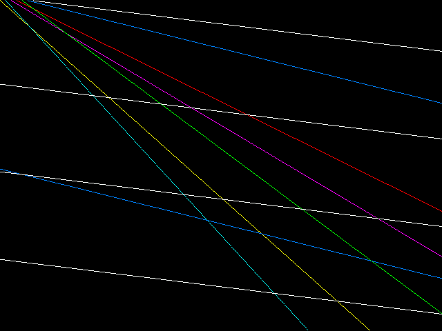
- 0003.png (6.63 KiB) Viewed 2042 times
Re: Concept & Design of 3.3V Parallel 16-bit VGA Boards
Posted: Mon Dec 10, 2012 6:38 pm
by ElEctric_EyE
I've tested for shorts on the /Program line on the 2 bare boards I have and found none.
I happened to download your newest github post about 30 min's ago. Works good, except when dy>dx. Also the white line looks 2 pixels thick. As you mentioned, I've also noticed the stray pixels on the very right edge, and flashing horizontal line on the very bottom.
Re: Concept & Design of 3.3V Parallel 16-bit VGA Boards
Posted: Mon Dec 10, 2012 6:45 pm
by Arlet
Yes, the "dotted" line when dy > dx is a known issue. It's not hard to fix, but I decided to work on other stuff first. The other bugs I have no idea yet what's causing them. The problem is that it takes a while to show up, and simulating more than a few frames is a pain, so I need to set the initial conditions such that the bug appears right away.
Of course, I also need to provide proper start and endpoints, instead of extending the lines all the way across the screen. I didn't notice anything exceptional in the white line, but I'll take a closer look.
Re: Concept & Design of 3.3V Parallel 16-bit VGA Boards
Posted: Mon Dec 10, 2012 7:05 pm
by ElEctric_EyE
If you add x <= x - 1 after line 107 of line.v module, negative slopes and dy>dx seem to work.
Re: Concept & Design of 3.3V Parallel 16-bit VGA Boards
Posted: Mon Dec 10, 2012 7:17 pm
by Arlet
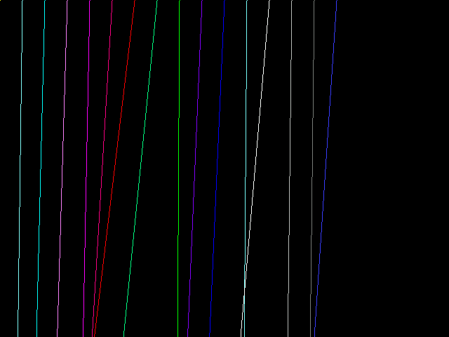
If you look closely, that results in stairstep patterns. Also I'm not supposed to have negative slopes yet

I've checked in a fix for the dy > dx case. I'll look at the other bugs after this.

- vertical.png (2.5 KiB) Viewed 2031 times
Re: Concept & Design of 3.3V Parallel 16-bit VGA Boards
Posted: Mon Dec 10, 2012 7:28 pm
by ElEctric_EyE
Interesting to note also, the "random" pixels on the right are gone. Maybe a clue there even though the x <= x - 1 is wrong...
Re: Concept & Design of 3.3V Parallel 16-bit VGA Boards
Posted: Mon Dec 10, 2012 7:59 pm
by Arlet
Fixed the flashing bottom scanline. I also don't see the stray pixels on the right anymore.
Edit: added support for negative dx, and added some more lines in the demo.
- 0004.png (3.03 KiB) Viewed 2020 times
Done for tonight, and I won't have any time tomorrow.
Re: Concept & Design of 3.3V Parallel 16-bit VGA Boards
Posted: Mon Dec 10, 2012 9:45 pm
by ElEctric_EyE
I was trying to add more lines too in order to see if it affected speed, I'll compare your code. Thanks!
I also traded out the DLL_SP for a PLL_BASE, even though the tools optimized it to a PLL_ADV. With the 7 lines the system can run @133MHz with 640x480 @25MHz pixel clock.
I got the resolution up to 1024x768 @71MHz pixel rate, but the system clock max with 7 lines is about 88MHz. It was a quickie test and it ran, but without switching all other parameters in your code, you can imagine it looks like a mess, but I could see the general behavior well.
I will try your new code now and observe top speed limitations at both resolutions.
Re: Concept & Design of 3.3V Parallel 16-bit VGA Boards
Posted: Mon Dec 10, 2012 10:01 pm
by ElEctric_EyE
Ah sweet! I kept the settings for 1024x768 and it still passes synthesis with no timing issues with the 16 lines.