Page 11 of 15
Re: Breaking 6502 apart
Posted: Mon Mar 11, 2013 12:42 pm
by org
I still can't fully understand execution order

In top part I have problems with flags input/outputs (still dont know what to do first - input flags from databus, or output current flag values)
In bottom part I have bunch of control lines which can lead to bus conflicts, for example :
If X/SB and Y/SB are become asserted at same time they encounter bus conflict (X and Y are put on SB at same time).
Re: Breaking 6502 apart
Posted: Mon Mar 11, 2013 1:07 pm
by BigEd
Ah, yes, outside of normal operation there could be bus conflicts - the undefined opcodes may do this - and you'll most likely get either an AND or an OR of the various writers.
Re: Breaking 6502 apart
Posted: Mon Mar 11, 2013 1:12 pm
by org
and you'll most likely get either an AND or an OR of the various writers
I will apply "ground wins" rule
BTW, I updated PSD sources too :
http://breaknes.com/files/6502/6502.zip [150 MB]
Re: Breaking 6502 apart
Posted: Wed Mar 20, 2013 5:36 am
by org
NMI pad logic
Transistor schematics:
Image no longer available: http://breaknes.com/files/6502/NMI_PAD0.jpg
Logic circuit:
Image no longer available: http://breaknes.com/files/6502/NMI_PAD1.jpg
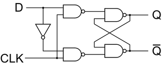
After removing inverters it turned out to be D flip/flop

Image no longer available: http://breaknes.com/files/6502/NMI_PAD2.jpg
Re: Breaking 6502 apart
Posted: Thu Apr 18, 2013 10:45 am
by org
- Complete decoder labels
- Fixed names for /T0, /T1X and T1 lines
Latest version here :
http://breaknes.com/files/6502/6502.jpg
Re: Breaking 6502 apart
Posted: Fri Apr 19, 2013 11:02 am
by org
Re: Breaking 6502 apart
Posted: Wed Apr 24, 2013 7:38 pm
by org
Re: Breaking 6502 apart
Posted: Wed Apr 24, 2013 8:30 pm
by BigEd
One small point - for a transparent latch, I've seen a symbol used where the clock input is marked with a half- square, instead of a triangle. The triangle means it's an edge-triggered flop.
Cheers
Ed
Re: Breaking 6502 apart
Posted: Wed Apr 24, 2013 9:04 pm
by zellyn
The triangle looks like half a square to me... :-p
Re: Breaking 6502 apart
Posted: Wed Apr 24, 2013 9:35 pm
by BigEd
Funny!
Re: Breaking 6502 apart
Posted: Thu Apr 25, 2013 4:55 am
by org
The triangle means it's an edge-triggered flop.
Thanks, didn't know this detail )
Those D-triggers are implemented as floating gate transistors. And its level-triggered of course. Is there any better way to represent it as logic block ?
Re: Breaking 6502 apart
Posted: Thu Apr 25, 2013 1:44 pm
by Dr Jefyll
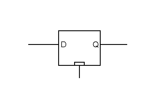
- latch_symbol.png (1.67 KiB) Viewed 1627 times
for a transparent latch, I've seen a symbol used where the clock input is marked with a half- square
Like this, then? Up until now I've just used "LE" to label such an input, but a symbol would be preferable.
Cheers,
Jeff
Re: Breaking 6502 apart
Posted: Fri Apr 26, 2013 12:28 am
by BigEd
That's exactly what I've seen before, thanks Jeff. I couldn't find it though. What I did find was the idea of using a plain input called "E" instead of a triangle-marked input.
Cheers
Ed
Re: Breaking 6502 apart
Posted: Fri Apr 26, 2013 1:34 am
by Dr Jefyll
I couldn't find it though. What I did find was the idea of using a plain input called "E"
Ditto on both points! -- I did a search and found the "E" suggestion but not the symbol. So, I drew one myself. Glad you like it!
Re: Breaking 6502 apart
Posted: Fri Apr 26, 2013 5:08 am
by org
Fixed) I found "custom element" in circuitlab and made "E" input.