Page 2 of 8
Re: Mickey Mouse logic for address decoding?
Posted: Sat Jan 31, 2026 4:07 am
by richardc64
Cool that this should turn up just when I'm working on a design that needs one AND but has an unused OR.
The consensus appears to be that propagation delay would kill the whole enterprise unless you knew what you were doing. Well, that wouldn't be me.

Let's reason it out: The 1N4148 test figure suggests forward conduction occurs instantaneously, or nearly so, and reverse recovery is 4nS. Therefor the total high-to-low delay should be 0+ whatever the prop. delay of the device buffering the resistor-diode point is, and low-to-high should be reverse recovery+ the device delay -- a not unusual unequal tPHL and tPLH.
I haven't factored the resistor value, or the diodes' capacitance, or the gate's input C into my simplistic reasoning.
Re: Mickey Mouse logic for address decoding?
Posted: Sat Jan 31, 2026 4:38 am
by GARTHWILSON
I haven't factored the resistor value, or the diodes' capacitance, or the gate's input C into my simplistic reasoning.
Re: Mickey Mouse logic for address decoding?
Posted: Sat Jan 31, 2026 8:59 am
by barnacle
At the very least, the resistor current has to charge to 0.7v before the diode conducts (less for Schottky), and then start charging the following gate input capacitance.
Neil
Re: Mickey Mouse logic for address decoding?
Posted: Sat Jan 31, 2026 5:16 pm
by GARTHWILSON
Neil, I meant when the last diode turns off (not on), so the resistor can start pulling up and charging up the parasitic capacitances.
Re: Mickey Mouse logic for address decoding?
Posted: Sat Jan 31, 2026 9:10 pm
by barnacle
Ah, understood.
Neil
Re: Mickey Mouse logic for address decoding?
Posted: Sun Feb 01, 2026 5:58 pm
by Dr Jefyll
I haven't factored the resistor value, or the diodes' capacitance, or the gate's input C into my simplistic reasoning.
...and that right there is where the problem is.
I'll jump in here for a moment just to make clear that the delay resulting from the resistor isn't necessarily a show-stopper. It can very easily be mitigated by using a smaller (ie, lower resistance) resistor... but of course only within limits.
If the project is battery-operated then one limit is the amount power you're willing to dissipate during the time the diodes cause the resistor to conduct. This may or may not be critical. Obviously it'll work in your favor if the duty cycle -- the percentage of time the diodes cause the resistor to conduct -- is low.
Another limit is that, as you reduce the resistor value more and more, it gets harder and harder to drive the inputs of the MML "gate" because more and more current is required from the device doing the driving. Carried to extremes, this means the device won't be able to output a sufficiently high (or low) logic level. Therefore it's advantageous if said device has a comparatively strong output-current capability, as do 74AC Series devices for example.
Finally, there's a trick (shown below) that works only if the resistor is a pullup, not a pulldown (ie, the MML gate is an AND or NAND, not an OR or NOR). If the diode-resistor node drives one of the "T" logic families (74HCT, 74ACT etc) then we gain some wiggle room by in effect moving the goalposts.

"T" family devices have a lower input switching threshold, which means there'll be less time that elapses before the resistor pulls sufficiently high.

Just be careful to ensure that a satisfactory low state can be achieved. You'll definitely wanna use Schottky diodes (because of their lower voltage drop); this helps in meeting the lower input switching threshold of the "T" series device.
-- Jeff
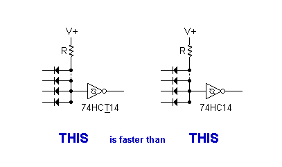
- mickey_mouse_logic.png (2.26 KiB) Viewed 267 times
Re: Mickey Mouse logic for address decoding?
Posted: Sun Feb 01, 2026 9:40 pm
by Michael
Question, please? Hopefully not too far off topic?
Is there a combination of diodes and active device (bjt, mosfet, 74HCT139 input, etc.) that could be used something like below for a 1-MHz system? I think it would be kind of cool to use 10¢ of small discrete parts tucked into the open frame of an IC socket on a small SBC.
Re: Mickey Mouse logic for address decoding?
Posted: Mon Feb 02, 2026 12:07 am
by Martin_H
@Michael, similar circuits have been discussed on the forum previously. I don't have a link to them, but Garth was one of the contributors and might.
If I recall correctly, you need a bias resistor at the base of the transistor. But you also need a capacitor in parallel to the bias resistor. The capacitor's inrush current improves performance at higher frequencies, while the resistor protects the transistor junction.
Re: Mickey Mouse logic for address decoding?
Posted: Mon Feb 02, 2026 1:42 am
by GARTHWILSON
It's an interesting circuit, using high and low inputs, but will be quite slow, at least 100ns. You'll need to test it, especially to find out the Miller effect on timing. There's also the time needed for the transistor to come out of saturation, a situation which prompted designers to put the Schottky diode from the collector to the emitter in logic ICs, to prevent saturation, which is why the output of TTLs only comes down to about 0.4V, not lower. If you're only interested in 1MHz, the idea might still be ok.
@Michael, similar circuits have been discussed on the forum previously. I don't have a link to them, but Garth was one of the contributors and might.
If I recall correctly, you need a bias resistor at the base of the transistor. But you also need a capacitor in parallel to the bias resistor. The capacitor's inrush current improves performance at higher frequencies, while the resistor protects the transistor junction.
The base-emitter breakdown voltage is usually quite low, like 5V. If one (or more) of the diode inputs is low and the emitter is pulled high, hopefully there won't be any breakdown. It might be close though. When I worked at a transistor manufacturer, testing the breakdown voltage was a regular part of production testing, on every single unit, not just spot testing. As with zener diodes, it does not damage the transistor to be given a small reverse current in the breakdown voltage curve, but I don't know what would happen if you have a situation where it's getting broken down regularly in use (as opposed to doing it quickly for a test and then never again). Zener diodes are of course designed to be used in that mode. I worked in applications engineering, not wafer fab, and I don't know the details of the various dopings and all that stuff that the physicists and chemists and chemical engineers would discuss in their huddles after we gave them the results of our tests on finished transistors in circuits like our customers would be using them in.
Re: Mickey Mouse logic for address decoding?
Posted: Wed Feb 11, 2026 2:18 am
by No True Scotsman
... a marvelous little pushbutton circuit I stumbled across decades ago, which does its own debouncing and provides a push-on, push off function using just a simple SPST pushbutton! The circuit appears in
this post, and the explanation appears 4 or 5 posts later.
I got to looking at this circuit more closely today and realized you're most likely not supplying power to a whole computer from the output an inverter.

The output of this circuit would have to control a MOSFET, relay, UDN2981, ULN2803, or some other actual power switch. I have a supply of
2N7000s on hand. Would that do the trick for a small 65C02 computer?
Re: Mickey Mouse logic for address decoding?
Posted: Wed Feb 11, 2026 3:00 am
by GARTHWILSON
... a marvelous little pushbutton circuit I stumbled across decades ago, which does its own debouncing and provides a push-on, push off function using just a simple SPST pushbutton! The circuit appears in
this post, and the explanation appears 4 or 5 posts later.
I got to looking at this circuit more closely today and realized you're most likely not supplying power to a whole computer from the output an inverter.
The output of this circuit would have to control a MOSFET, relay, UDN2981, ULN2803, or some other actual power switch. I have a supply of
2N7000s on hand. Would that do the trick for a small 65C02 computer?
Re: Mickey Mouse logic for address decoding?
Posted: Wed Feb 11, 2026 3:09 am
by No True Scotsman
The 2N7000 is an N-channel enhancement-mode MOSFET,... this transistor would not be the kind you want to turn the positive power supply on and off for your computer.
I was just thinking a P-channel would be better for this. I'm guessing a BS250 would work?
Do you have a complementary MOSFET or P-channel bipolar transistor you could use with it?
I unfortunately don't have a BS250, nor any other P-channel FET, unless one is lurking in my BJT assortment that I don't know about. I do have the aforementioned UDN2981 and ULN2803 ICs, one of which is a low-side driver and the other a high-side driver. I don't want to use a whole chip for one channel though. What BJT would you recommend?
Re: Mickey Mouse logic for address decoding?
Posted: Wed Feb 11, 2026 3:22 am
by No True Scotsman
I do have the aforementioned UDN2981 and ULN2803 ICs, one of which is a source driver and the other a high-side driver. I don't want to use a whole chip for one channel though.
I can, however, imagine a mad power management scheme in which a UDN2981 is used to individually power chips on and off. Whether that's advisable would be a different story.

Re: Mickey Mouse logic for address decoding?
Posted: Wed Feb 11, 2026 6:08 am
by GARTHWILSON
What's the maximum amount of current you anticipate your circuit taking? You'll want a transistor that will not drop significant voltage at that amount of current, meaning also that you won't want a Darlington type.
As for turning individual ICs off and on, remember that if these have logic lines connected to them, it's generally not desirable to have those go high while the IC is not powered up. You probably won't hurt anything, but these ICs will probably have input-protection diodes which, when the input voltage goes above their power-supply voltage, will conduct, and power up the IC to some extent, which may have various interesting effects which won't be helpful.
Re: Mickey Mouse logic for address decoding?
Posted: Wed Feb 11, 2026 6:55 pm
by L0uis.m
Hello 01 all,
For (possibly) even smaller logic than M²L, check out Min(n)i(e) Mouse Logic
 viewtopic.php?f=4&t=8553
