Page 2 of 5
Re: 74HCT6526 SBC TestBed
Posted: Mon Jan 20, 2020 5:11 am
by Michael
Oh my goodness... Just spotted a big blunder thanks to BDD's comments. Replacing U10a with a pair of 74AC00 gates doesn't really shave anything off the propagation delay, however, driving the 74AC138 directly with the A15 and A14 lines provides a big gain...
My apologies for missing this, dani.
Re: 74HCT6526 SBC TestBed
Posted: Mon Jan 20, 2020 7:46 am
by Michael
dani, I just noticed your PIC 16F628A Frequency Counter in the updated schematics in post #2. If I had known you were familiar with PIC microcontrollers I would have suggested using a PIC for your Adjustable Clock circuit and display early on. Gosh, there are so many different ways you can generate, control, and display an adjustable clock. May I provide an example if your head hasn't exploded yet (grin)? This example would replace the 16F628A frequency counter and eliminate the 74ABT74 and the 74AC14 chips... The crystal is an Epson CA-301 8.388608M-C (
DigiKey part # SER3415-ND, $0.83 each) which is used to provide a nice round 16.0-Hz increment for the PIC 20-bit NCO (Numerically Controlled Oscillator) module. If you order one of these crystals, would you get an extra for me, please? Also, I'd be happy to help with the PIC program (and programming if you don't have a PICKIT3 programmer).
Cheerful regards, Mike
Re: 74HCT6526 SBC TestBed
Posted: Mon Jan 20, 2020 8:48 am
by daniMolina
Jikes! You've been busy tonight!
I'm not sure how important performance is to you, but if it were me I'd be using a 74AC00 in place of the 74AC139 (U10). The average prop time of one section of an 'AC00 is about half of the 'AC139. This isn't too important a consideration with U10b, but could matter with U10a.
It's important, as I want to go as high as possible. Being my first take at an SBC, I won't it to reach too far. Moreover, once I connect my
74HCT6526, I'm pretty sure it will be the limiting factor. Anyway, as Michael pointed out later, going with an 'AC00 may not provide too much benefit. One of my first desings had 3 NAND gates to generate the /CS for the Ram.
ETA: the output of U9a as wired is an active-high signal. Is that what the LCD module requires? Just checking...
Yes, it's active high. Also, I was just going through the datasheet for the LCD and don't think it can go very fast... don't really think it can even do 1 MHz! I may end driving it up with the peripheral ports in the 6522 or the '6526, so I can control its timing via software.
I see a 74ABT74 is being used as the source for /PHI2 and PHI2. That flop should be a 74AC74
Agreed. All parts should be AC. I didn't pay too much attention at first to the logic family of the ICs and just focused on the logic. I have some early screenshots where I still have some LS ICs

Oh my goodness... Just spotted a big blunder thanks to BDD's comments. Replacing U10a with a pair of 74AC00 gates doesn't really shave anything off the propagation delay, however, driving the 74AC138 directly with the A15 and A14 lines provides a big gain...
Again... so obvious! Finding
a solution is easy... Finding the
optimal solution is an art.
If I had known you were familiar with PIC microcontrollers
Not at all. Actually, is the part I'm less familiar with of this whole idea, and I'm pretty unfamiliar with almost everything. The frequency meter is based on a cheap kit sold on
Aliexpress, which is pretty much a rip-off of
this. The kit comes with the PIC preprogrammed so, I'm just hoping I'll be able to adapt it to my needs.
Cheers!
Re: 74HCT6526 SBC TestBed
Posted: Mon Jan 20, 2020 7:37 pm
by daniMolina
Yes, it's active high. Also, I was just going through the datasheet for the LCD and don't think it can go very fast... don't really think it can even do 1 MHz!
Sorry for quoting myself, but I wanted to clarify on this.
After digging through the LCD datasheet, it seems it may barely do 1 MHz, but I'm not even sure of that. The minimum time for the LCDE pulse is 230ns. The single addres line, and the R/W, have to be setup 40ns prior to that... so nay, I can't drive it from the main bus. What can you expect from a 2.5$ LCD display, shipping included!
I've seen a video from the 8-bit guy on which he connected an LCD to a C64. First, via the user port (So, driving it with the CIA) then via the expansion port, directly attached to the computer bus. Some glue logic was needed to make it work. He didn't go into details, but I'm guessing some latches maybe?
Anyway, I've attached the LCD to the 6526 PortA. I just feel like a real hardware engineer now. Just passed the issue to a poor software engineer

As a bonus, I'm posting my first attempt at the PCB.
As usual, 10cm x 10 cm, 2layer board. The cheapest I can have manufactured. If I find it to work at low speeds, I'll probably get a 4-layer version afterwards.
Re: 74HCT6526 SBC TestBed
Posted: Mon Jan 20, 2020 7:54 pm
by GARTHWILSON
daniMolina, note that the common intelligent character LCD modules need more than meets the eye to make the setup work consistently. I cover this in the sample code linked in the 6502 primer, at
http://wilsonminesco.com/6502primer/LCDcode.asm . The first time I used one of these LCDs, it was on a 65c02 computer that ran very slowly to conserve battery power (the entire computer only took 2mA, including the LCD), so it was ok to put the LCD directly on the bus; but after that, I always went through a 65C22 VIA. You can take the same code and modify it for your '26.
Re: 74HCT6526 SBC TestBed
Posted: Tue Jan 21, 2020 1:51 am
by Chromatix
A 230ns access time with 40ns setup should work on the 6502 bus up to about 2MHz, if you do it properly. The R/W and A0 signals are valid from the 6502 by the end of Phi1, which takes care of their setup time. Then you only need the access strobe to be qualified by Phi2.
Of course, if you want to run faster than that, you'll need to either insert wait-states, or insert some sort of buffer to isolate the device from the bus.
Re: 74HCT6526 SBC TestBed
Posted: Tue Jan 21, 2020 5:09 am
by Dr Jefyll
An alternative to wait-states is Clock Stretching. Both are feasible, but Clock Stretching probably requires fewer IC's, assuming jelly-bean logic is used. In my
RDY vs CLOCK STRETCHING post there's a clock-stretch circuit that requires just one 16-pin IC. And it lets you run your CPU at or near its full speed potential.

Tonight I updated the post, after realizing it failed to address daniMolina's requirement for extra setup time for the LCD. Others will face the same issue in future. The matter is now corrected. Extra sets of eyes welcome, but I think my Clock-Stretch mod solves the LCD problem, and still only requires one IC. As a bonus it's possible the capability for clock-stretching may also come in handy elsewhere in the project.
( I'm not necessarily arguing that this is the "best" solution -- "best" will depend on many factors. I'm just drawing attention to one possible option. )
-- Jeff
Re: 74HCT6526 SBC TestBed
Posted: Tue Jan 21, 2020 9:58 am
by daniMolina
So far, I've completely ignored RDY. I do have some notions of what it does and how it works, but don't fell too comfortable with it... yet
I'm going to keep the hardware side as simple as I can for now. The chances of nothing working at first are still high and the fewer things I have to troubleshoot, the better.
Still, I'm bookmarking your post. I understand waiting for slower devices is an elegant way of doing this kind of stuff, and will probably add this in a 2nd revision of my SBC, if I ever get that far.
Thx!
Re: 74HCT6526 SBC TestBed
Posted: Tue Jan 21, 2020 4:16 pm
by BigEd
I think these LCDs have always been a bit slow.
One of the ways Acorn's BBC Micro deals with slow devices is to hang them off a 'slow' bus which uses a VIA: one port is a data bus and (some bits of) the other port is an address bus. And perhaps a strobe... Anyway, it's a way to connect devices which demand a slower access.
Re: 74HCT6526 SBC TestBed
Posted: Tue Jan 21, 2020 5:21 pm
by cjs
One of the ways Acorn's BBC Micro deals with slow devices is to hang them off a 'slow' bus which uses a VIA: one port is a data bus and (some bits of) the other port is an address bus.
So basically you wire all your peripheral chips' data pins in parallel on the "data" bus, run two or three bits of the other port as the "address" bus for selecting registers, and use the rest of the bits for chip select (maybe through a '138 or similar if you need lots of CS lines)? That's clever!
Re: 74HCT6526 SBC TestBed
Posted: Tue Jan 21, 2020 5:37 pm
by BigEd
Indeed - but only slow devices which are not performance-critical! I think that turns out not to be a redundant description. For example, sound and speech chips need only infrequent access, as does the keyboard.
http://8bs.com/inbbc.htm#IC3
(The 2MHz Beeb also does clock-stretching to access 1MHz devices. The later Master uses RDY for the same purpose.)
Re: 74HCT6526 SBC TestBed
Posted: Tue Jan 21, 2020 5:44 pm
by Michael
Have you considered using an LCD 'Backpack' of some sort? Serial, I2C, and various shift-register designs have been popular for years. I've even contributed a few designs. I'd like to think I came up with the first 2-pin shift-register backpack design that used 8-bit LCD interface mode (below).
Cheerful regards, Mike
Re: 74HCT6526 SBC TestBed
Posted: Tue Jan 21, 2020 8:22 pm
by daniMolina
A solution very similar to this is shown, at least an schematic, in the 8-Bit Guy series on LCD screens
part 2.
.
Again, I think this makes for simpler hardware, more complicated software. Everything in this world is a compromise between different variables.
As the hardware is, for sure, my weakest point, at least right now, I'd rather stick with the simplest design. Don't get me wrong, I find your ideas brilliant, and I'm taking good notes of them.
Taking an optimistic note, if the LCD interface is generating the most debate here, that means the rest of my SBC is pretty much OK
Cheers!
Re: 74HCT6526 SBC TestBed
Posted: Tue Jan 21, 2020 9:02 pm
by drogon
A solution very similar to this is shown, at least an schematic, in the 8-Bit Guy series on LCD screens
part 2.
multidevice.PNG
.
Again, I think this makes for simpler hardware, more complicated software. Everything in this world is a compromise between different variables.
As the hardware is, for sure, my weakest point, at least right now, I'd rather stick with the simplest design. Don't get me wrong, I find your ideas brilliant, and I'm taking good notes of them.
Taking an optimistic note, if the LCD interface is generating the most debate here, that means the rest of my SBC is pretty much OK
Cheers!
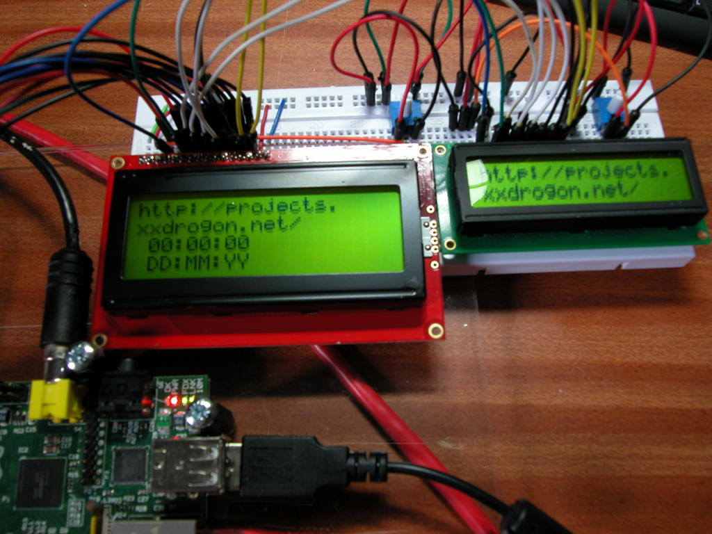
I used this "trick" some (eek, 8!) years back on the Raspberry Pi. It works very well:
https://projects.drogon.net/wp-content/ ... pi2lcd.jpg
That image shows them in 8-bit mode, but 4-bit mode is fine too.
Be aware that the cheap "clones" often don't have the extra character RAM to allow user-defined characters...
-Gordon
Re: 74HCT6526 SBC TestBed
Posted: Thu Jan 23, 2020 6:11 pm
by daniMolina
Updated schematics, with just some minor tweaks. A couple of gate swaps to improve on routing, and connected 6526 PB low nibble with 6522 PA low nibble, in the hope of creating a parallel communication port between them, using CA1, CA2, /PC and /FLAG as handshaking signals.
PCB is getting some minor updates too... but I'm pretty much satified with it. Pretty solid ground plane, almost no vias on main signals... and it looks nice too. I have exposed via a header PB4-PB7 from the 6522. I'm thinking about putting 4 push buttons there so I can have minimal input too.
Beside this, I don't expect anything much to happen for the next 3-4 weeks. I'm on the hunt now for all parts, and as they arrive, I'll start some test to validate the design.
I'll probably start with the following, in no particular order
- clock generator
- RAM bootstrap with arduino
- NOP loop, after filling the RAM with EAs
- Frequency meter
- Write something to the LCD
I want to leave you a question that's been around my head, let me know what do you thing. What are the odds (Assuming there're no errors in my design, of course) that an old, NMOS 6526 will work here? I know it's a TTL device againts an army of CMOS parts, however, I recall reading somewhere that, if there's no need to drive too many stuff, there's a chance a single TTL device has enough power to pull up strong enough to be able to talk with CMOS parts.
I guest the "by the book" answer is, no, it shouldn't work and probably won't. The real answer, I think, is somethine like a maybe, but unreliably. It may even depend on the specific 6526 I use. I have plenty to torture, so I will try it anyaway at some point
Cheers!