Page 2 of 3
Re: Cassette Interface Circuit for Homebrew Computer
Posted: Tue Sep 18, 2018 8:15 pm
by barrym95838
The Apple interface is about as simple and unreliable as you can get.
In my personal experience, the TRS-80 Model I was the worst (slowest and least reliable). The C=64 was meh, and the Apple ][ was slightly better than meh. Floppy disks were a big upgrade for any of those three systems, but I upgraded my ][+ to the Disk ][ (as soon as I could afford it) not for reliability reasons, but for raw speed ... and the Disk ][ delivered plenty.
Re: Cassette Interface Circuit for Homebrew Computer
Posted: Tue Sep 18, 2018 9:23 pm
by GaBuZoMeu
This is the circuit used for the Acorn Atom cassette input:
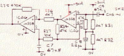
- file.png (155.9 KiB) Viewed 3985 times
This works well at 300 baud, and less well at 1200 baud.
The output (on the left hand side) is TTL-compatible, and on the Atom connects to an input of an 8255 PIA.
The complete Atom schematic is here:
https://acorn.huininga.nl/pub/docs/circ ... iagram.gif
Dave
I'm sure with a proper opamp like LMC6482 this circuit should work fine for any baudrate. The LM358 is simply too slow.
Regards,
Arne
Re: Cassette Interface Circuit for Homebrew Computer
Posted: Tue Sep 18, 2018 11:24 pm
by BillO
What does the output circuit look like?
Edit: Never mind - I found it.

Re: Cassette Interface Circuit for Homebrew Computer
Posted: Tue Sep 18, 2018 11:36 pm
by zx80nut
Hi.
Sorry that my pages were down. Glad you found them on archive.org. There was an issue on the web hoster side that wrongly flagged an issue with my site. All back up and running now
 http://searle.hostei.com/grant/6502/Simple6502.html
http://searle.hostei.com/grant/z80/SimpleZ80.html
http://searle.hostei.com/grant/6502/Simple6502.html
http://searle.hostei.com/grant/z80/SimpleZ80.html
etc...
Grant
Re: Cassette Interface Circuit for Homebrew Computer
Posted: Tue Sep 18, 2018 11:44 pm
by BigEd
Just for amusement, or amazement, follow Mats Engstrom as he creates a tape decoder entirely from discrete components:
https://github.com/SmallRoomLabs/KCSviewer#readme
Re: Cassette Interface Circuit for Homebrew Computer
Posted: Wed Sep 19, 2018 1:06 am
by 1024MAK
@Johnny
Another option is to either use a Commodore Datasette C2N/1530/1531 (TTL data inputs and outputs) or use the circuits from one. Schematics are
here
Mark
Re: Cassette Interface Circuit for Homebrew Computer
Posted: Wed Sep 19, 2018 12:06 pm
by Tor
I only had trouble when I used the cassette interface on a Dragon 32 I did some "contractual" programming on. So I saved every program 3 times on the same tape, on a couple of tapes, that was the only way to have any hope of retrieving the previous day's work.
But then again, something like the Apple interface (or the KCS, but I don't know it well) is something one can have fun fiddling with, trying to improve the reliability. If you have a 'scope, at least.
Re: Cassette Interface Circuit for Homebrew Computer
Posted: Wed Sep 19, 2018 2:37 pm
by BigEd
One of the nice things about Acorn's format for the BBC Micro was that it was block-based, with a header and a CRC for each block. If a CRC error was detected, you could see which block number was broken, rewind and try again. You could even swap tapes and load the block from another tape: the routine would ignore any block which isn't the next one it needs.
There is of course some extra overhead for this approach: again, a tradeoff for robustness.
As you'd imagine, a block was 256 bytes.
Re: Cassette Interface Circuit for Homebrew Computer
Posted: Wed Sep 19, 2018 6:48 pm
by whartung
You'd think such a circuit and interface would be pretty simple. Demonstrably, it IS rather simple. It's just interesting that it's so difficult to actually get right and robust.
The differences in tape speeds is a situation I hadn't really thought of.
Re: Cassette Interface Circuit for Homebrew Computer
Posted: Wed Sep 19, 2018 7:52 pm
by BigEd
Some interesting notes here on phase shift:
http://beebwiki.mdfs.net/Acorn_cassette ... hase_shift
Any tone-based system has a chance of being immune to phase shifts, but an edge-based system might get into trouble.
Re: Cassette Interface Circuit for Homebrew Computer
Posted: Thu Sep 20, 2018 12:05 am
by GaBuZoMeu
Any tone-based system has a chance of being immune to phase shifts, but an edge-based system might get into trouble.
As long as you are well below the upper corner frequency of the used tape deck and cassette the phase shift should be constant. A "tone-based" system - as I read it - depends on the frequency - or period - of the signal. That means it measures the time between two transitions of the
same direction. An advanced software would use a sync header to adapt to the actual frequency (depending on the absolute and momentary tape speed) and readjust that timing value during read - within some limits of course.
Any "edge-based" system would have serious trouble if it strictly depends on the polarity of the edges. But if it uses the sync header to adapt to the actual polarity it compensates any phase shift between some "original" and the given signal. The robustness depends on how much tolerances this edge triggered method allows for the occurance of the other edge.
A special case IMHO is the situation when the recording software generates one full wave to represent one bit level (say a "1") and one half wave of half that frequency to represent the other bit level (a "0"). You may understand this as a frequency shift modulation (high frequency => 1, low frequency => 0) or as a pulse positioning modulation (transition occured => 1, not occured => 0) as well. Again the reading software should be capable to adapt to the edge polarity and the period to tolerate absolute and momentarily tape speed variations.
In all cases a good signal conditioning is helpful. The Acorn schematic hoglet has presented is such one (and can be enhanced using a somewhat faster opamp). A moderate amplification of the AC signal followed by a Schmitt-Trigger with a moderate positive feedback. This avoids multiple transitions when crossing zero and allows huge amplitude modulations (dropouts) without consequences. The phase shift of this circuit is acceptable within the frequency range of interest (40° from 500Hz...10KHz).
Regards,
Arne
Re: Cassette Interface Circuit for Homebrew Computer
Posted: Thu Sep 20, 2018 12:56 am
by GARTHWILSON
From this post (I had forgotten about it, but the page there is relevant to the tape discussion):
- I had worked as a repair tech at TEAC a few years earlier, and I aligned every machine when I was done with it. I was quite familiar with the poor performance of cassettes, which might not be what you'd expect. <snip>
Also, at 0VU, cassettes' frequency response is terrible. It only goes to about 4kHz. You might look at the specs on your expensive home-entertainment cassette machine and see something like 16kHz; but that's always measured at extremely low levels, like -40VU, so as not to scare the prospective buyer away. <snip>
Another problem for typical cassette data circuits is that at high frequencies, the phase is all over the place because of poor tape handling in the shell and not moving the tape fast enough for the amount of flexibility of the tape itself. If you play the left and right channels into the X and Y inputs of an oscilloscope and get a Lissajous pattern at high frequencies, what you'll see is like scribbling all over the center of the screen, because of the bad phase behavior and inconsistent output level. The poor phase response undoubtedly contributes to the error rate in the way some cassette data circuits were designed.
OTOH, the open-reel machines gave solid, steady tones at 20kHz and 0VU. There was no need to hide the truth by manipulating the specs.
Open-reel does so much better because of thicker tape and better tape handling which make the tape's movement over the heads much smoother and more even, and of course does better in the frequency response, noise, and dropouts department because of higher tape speed and wider tracks. Now if you really wanted vintage, you could use one of those popular small, portable open-reel machines with 3" reels, like what showed up in the "Get Smart" TV series, being used to store data, even before the Compact Cassette came out!  I have one I bought several years ago just for the historical value. It still works. It looks like this:
It was cheap and definitely not an example of good performance though, even for its time.
Re: Cassette Interface Circuit for Homebrew Computer
Posted: Thu Sep 20, 2018 5:11 pm
by whartung
Well it should be noted, especially regarding Garth's post, that some of the unreliability of cassette tape wasn't so much manifest when used locally, on the same recorder, but when sharing tapes with others. The tolerances of different recorders, especially consumer recorders in all sorts of weather conditions, were pretty broad.
While getting a tape to save and load on your own system may have worked fine, trading the tapes was potentially another story.
Re: Cassette Interface Circuit for Homebrew Computer
Posted: Tue Oct 02, 2018 1:43 pm
by Jeff_Birt
I picked up an old TI-95 Procalc and was looking for the CI-7 tape interface but they are as rare as hen's teeth. With some internet searching I found a picture of one (both sides of the PCB) and the pins used on the expansion connector. Basically the CI-7 is just the circuit like you all have been describing above.
Then it occurred to me that I have several Commodore C2N Datasettes which is a generic tape mechanism with the proper electronics already built it. It uses a card edge connector to connect to a C64/VIC20 so I machined out a simple 1 sided PCB to plug into the connector and dug some .2" pitch terminal blocks out and soldered to the other end of the CPB to make connecting to it for testing easy.
The C2N (and its 1,000 clones) requires 6V for the motor and 5V for the logic. It also has a key sense switch that goes low when you press PLAY, FF, REW. The C64 controls the 6V for the motor with a high side switch (Darlington pair). My initial testing shows that while playing/FF it draws about 60ma from the 6V line and in REV this goes up to 160ma until the tape stalls at the end where it jumps to 250ma.
I dug out a 0.1" female header last evening to make the connector to the TI-95 so I can try some actual saving/loading form the calculator. In this usage case you can power the calculator from an external 6V source via the expansion connector so I can use one power supply for everything (just need a LDO regulator to give 20ma or so at 5V for the tape electronics.)
So, my point is that using such a tape deck as the C2N makes the job much, much easier. They are plentiful and cheap and you can get new belts for them. This should make adding cassette tape storage to a homebrew system or something like my calculator fairly easy.
The high side switch is bit of a pain. I was scrounging around my junk box for something like a TIP-125 (PNP Darlington pair) but came up empty. I did find a tiny 5V relay though which should work. This part is not really needed but the idea is that you position the tape to where your program is and when you type 'load' it the computer will turn off the 6V to the deck and ask you to press play. It senses when you press play and then turns the power on. This lets the computer turn the tape deck motor on/off as it needs to for the loading/saving/verifying process.
Re: Cassette Interface Circuit for Homebrew Computer
Posted: Tue Oct 02, 2018 2:25 pm
by BillO
There has to be any number of logic-level P-channel mosfets available for the motor switch. An NDP6020P comes to mind.