Page 2 of 4
Re: My Arduino-Based 6502 Simulation/Emulation...thing?
Posted: Sun Dec 02, 2012 7:43 am
by halkun
Hey there!
Well, another weekend and another chance to work on the project. I made some upgrades, but I may need some help to make sure I implemented everything properly. The first thing I did upgrade the emulation core. I can now service BRK interrupts, and added a few unimplemented opcodes. After that, I implemented the 65C02 instruction set. However, as my code-fu is quite week, I was wondering if anyone can look over the emulation core code just to make sure I implemented it correctly. Here is a list of what has changed
6502 opcodes I implemented:
00 BRK (?)
6C JSR (ind) (?)
78 SEI
58 CLI
40 RTI
New 65C02 opcodes I implemented:
ADC (zp) #done
AND (zp) #done
CMP (zp) #done
EOR (zp) #done
LDA (zp) #done
ORA (zp) #done
SBC (zp) #done
STA (zp) #done
BIT imm #done(?)
BIT zp,X #done
BIT abs,X #done
DEC A #done
INC A #done
JMP (abs,X) #done(?)
BRA LABEL #done
PHX #done
PHY #done
PLX #done
PLY #done
STZ zp #done
STZ zp,X #done
STZ abs #done
STZ abs,X #done
TRB zp #done(???)
TRB abs #done(???)
TSB zp #done(???)
TSB abs #done(???)
If you notice, some of the opcodes have question marks after the #done. This means I'm not quite sure I implemented it properly and might need to have someone check if I botched it up. I also didn't implement the Rockwell-only 65C02 opcodes either.
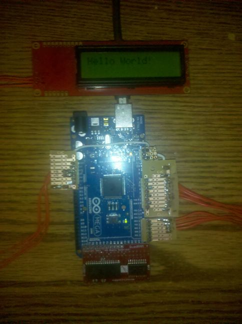
The other big thing is I found a way to import a binary compiled with ca65 into the code so I can implement my own "rom" now. As a test case I created this program.
Code: Select all
bsout	= $fc		; KERNAL ROM, output a character to current device.

	.org $0200

	ldx #0		; Starting index 0 in X register.
printnext:
	lda text,x	; Get character from string.
	beq done	; If we read a 0 we're done.
	sta bsout	; Output character.
	inx		; Increment index to next character.
	bne printnext	; Repeat if index doesn't overflow to 0.
done:
	jmp done		; loop forever

	.rodata

text:
	.byte	"Hello World!",0
and here is a picture of it running my my little piece of hardware.
I attached the new core... I hope it proves useful. Could use some feedback too. I'm one of the things I'm thinking of is moving the "hardware" registers out of the zero page and putting them at 0x200. I also may add the ability to read/write to the 4k EEPROM in the system as well.
Re: My Arduino-Based 6502 Simulation/Emulation...thing?
Posted: Sun Dec 02, 2012 8:18 am
by GARTHWILSON
I'm not very conversant in C (I assume that's what that is), so I would definitely miss a lot. But you wrote:
I also didn't implement the Rockwell-only 65C02 opcodes either.
Note however that current-production WDC 65c02's implement all the Rockwell instructions, plus STP (stop, op code DB) and WAI (wait, op code CB).
Re: My Arduino-Based 6502 Simulation/Emulation...thing?
Posted: Sun Dec 02, 2012 8:30 am
by halkun
RMB and SMB seem gangly to implement, and STP/WAI only work if there is a functional IRQ/NMI. My system doesn't implement hardware interrupts, short of a somewhat functional reset. When I start writing/porting code to my little system, if those opcodes are needed, I'll add them in.
Re: My Arduino-Based 6502 Simulation/Emulation...thing?
Posted: Sun Dec 02, 2012 9:39 am
by BigEd
Hi halkun! Did you run Klaus' test suite (now linked at
http://6502.org/tools/emu/)? It's found a few bugs in a few emulators.
Cheers
Ed
Re: My Arduino-Based 6502 Simulation/Emulation...thing?
Posted: Sun Dec 02, 2012 5:56 pm
by halkun
That tool only tests the 6502 opcods and none of the cmos versions. However, it not a bad endeavor to run it up on my little thing just to watch it fail in spectacular ways.

Re: My Arduino-Based 6502 Simulation/Emulation...thing?
Posted: Tue Dec 04, 2012 5:27 am
by halkun
Update!
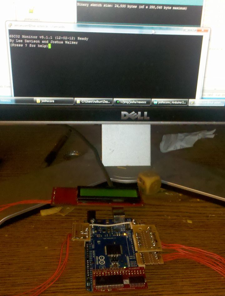
After fighting with a nasty stack pointer bug in the core for a few days, I now am in the way to porting 8bit's SBC-2 OS firmware to ca65. I'm porting it because I run win7 x64 and TASS will not run in that environment. I'm also putting my name in there, as a ca65 port is more than just adding a few assembler directives. I'm converting it to use the full blown toolchain with makefiles, linker configs and all. (It compiles under Cygwin)
Here is a preliminary screenshot. (Sorry for the messy desk!)
Re: My Arduino-Based 6502 Simulation/Emulation...thing?
Posted: Tue Dec 04, 2012 6:31 am
by BigDumbDinosaur
...STP/WAI only work if there is a functional IRQ/NMI.
True of WAI, but not STP (SToP). Following STP, the MPU halts when Ø2 goes high and stays halted until the RESB input is asserted. All registers except PB (65C816), PC and SR are preserved. From the W65C816S data sheet:
- 7.14 Stop-the-Clock (STP) Instruction
The STP instruction disables the PHI2 clock to all internal circuitry. When disabled, the PHI2 clock is held in
the high state. In this case, the Data Bus will remain in the data transfer state and the Bank address will not
be multiplexed onto the Data Bus. Upon executing the STP instruction, the RESB signal is the only input
which can restart the processor. The processor is restarted by enabling the PHI2 clock, which occurs on the
falling edge of the RESB input. Note that the external oscillator must be stable and operating properly
before RESB goes high.
I've verified on my POC unit that the MPU behaves exactly as described following the execution of an STP instruction.
Re: My Arduino-Based 6502 Simulation/Emulation...thing?
Posted: Tue Dec 04, 2012 6:33 am
by BigDumbDinosaur
...Here is a preliminary screenshot. (Sorry for the messy desk!)
Do I see potato chips pieces on the desk at the base of the video monitor? 
Re: My Arduino-Based 6502 Simulation/Emulation...thing?
Posted: Wed Dec 05, 2012 4:41 am
by halkun
I seem to have run across something strange...
In the SBC-2 OS code there is a really strange indirect mode that's causing ca65 to throw an error... I don't understand what it's trying to accomplish
Here are some examples...
Code: Select all
Input_chr      jmp   (ChrInVect)       ;
Scan_input     jmp   (ScanInVect)      ;
Output         jmp   (ChrOutVect)      ;
I simply replaced these routines as so and that fixed that...
Code: Select all
Input_chr:		lda Serial_read
				beq Input_chr
				rts

Scan_input:		lda Serial_read
				rts

Output:			sta	Serial_write
				rts
however, I'm getting some odd opcodes later on...
Code: Select all
Help_cmd3:      lda   (addrptr)         ;
               bne   Help_cmd4         ;
               rts
I'm getting an "illegal addressing mode" error on the lda.. What is it trying to get here?
Same thing here too...
Code: Select all
Insert_0:       LDA   (memptr)          ;
               STA   (Hexdigits)       ;
               lda   #$FF              ;
               DEC   Hexdigits         ;
               cmp   Hexdigits         ;
               BNE   Insert_1          ;
               DEC   Hexdigits+1       ;
It's choking on the first LDA with the odd addressing mode again.
also here too...
Code: Select all
lda (startaddr) ; get opcode of 4byte code
is it trying to load the value @ "startaddr" why no use "LDA startaddr"? What it's doing doesn't fit into the allowed addressing modes for LDA. What should I replace this opcode with?
Re: My Arduino-Based 6502 Simulation/Emulation...thing?
Posted: Wed Dec 05, 2012 6:25 am
by GARTHWILSON
I'm not familiar with the ca65 assembler, but is it NMOS only? LDA(ZP) (op code B2) was not on the NMOS 6502. JMP(abs) (op code 6C) was though.
is it trying to load the value @ "startaddr" why no use "LDA startaddr"?
It's the indirect, so it goes to "startaddr" to get the
address of the number it
really wants, then it reads that address it got from "startaddr". IOW, the processor will read two bytes for the instruction and operand, then
three more bytes, those being the two bytes needed to form the absolute address of the final target to read, plus that final target itself. The NMOS 6502 had LDA(ZP,X) (op code A1) and LDA(ZP),Y (op code B1) but no LDA indirects without pre- or post-indexing.
Re: My Arduino-Based 6502 Simulation/Emulation...thing?
Posted: Wed Dec 05, 2012 1:24 pm
by 8BIT
I seem to have run across something strange...
In the SBC-2 OS code there is a really strange indirect mode that's causing ca65 to throw an error... I don't understand what it's trying to accomplish
Here are some examples...
Code: Select all
Input_chr      jmp   (ChrInVect)       ;
Scan_input     jmp   (ScanInVect)      ;
Output         jmp   (ChrOutVect)      ;
This copies the Apple ][ by placing the IO routine jump vectors in RAM so you can change them on the fly. By default, the IO goes to the RS-232 terminal. If you add a video display, you could replace the ChrOutVect with the address of the Video output routine. This is how IN#2 and PR#2 worked. Your fix below works, but you lose the ability to remap your IO.
I simply replaced these routines as so and that fixed that...
Code: Select all
Input_chr:		lda Serial_read
				beq Input_chr
				rts

Scan_input:		lda Serial_read
				rts

Output:			sta	Serial_write
				rts
however, I'm getting some odd opcodes later on...
Code: Select all
Help_cmd3:      lda   (addrptr)         ;
               bne   Help_cmd4         ;
               rts
I'm getting an "illegal addressing mode" error on the lda.. What is it trying to get here?
This is fetching the text for the help command (?). Since the text is larger than 256 bytes, I just increment addrptr for each byte vs. using the NMOS opcode lda (addrptr),y opode and incrementing y. Yes, this is a CMOS opcode as the SBC-2 used the WDC 65C02 processor. You could set y=0 and use the NMOS opcode.
Code: Select all
Help_cmd3:  ldy #$00
               lda   (addrptr),y         ;
               bne   Help_cmd4         ;
               rts
Same thing here too...
Code: Select all
Insert_0:       LDA   (memptr)          ;
               STA   (Hexdigits)       ;
               lda   #$FF              ;
               DEC   Hexdigits         ;
               cmp   Hexdigits         ;
               BNE   Insert_1          ;
               DEC   Hexdigits+1       ;
It's choking on the first LDA with the odd addressing mode again.
also here too...
Code: Select all
lda (startaddr) ; get opcode of 4byte code
is it trying to load the value @ "startaddr" why no use "LDA startaddr"? What it's doing doesn't fit into the allowed addressing modes for LDA. What should I replace this opcode with?
I would have to check to be sure Y is not being used for some other feature. if it is not, then simply add the LDY #$00, LDA (zpaddress),y STA (zpaddress),y where zpaddress is the same label as the original source. If Y is being used for something else, then you will need to save it before the loop and restore it after.
I hope this helps.
Daryl
Re: My Arduino-Based 6502 Simulation/Emulation...thing?
Posted: Thu Dec 06, 2012 8:53 pm
by halkun
Well it turns out that ca65 does support that indexing mode, The real probelm was that my assembler uses labels that are case-sensitive. I fixed that and it compiled! I was even greeted with the prompt and everything!
Then I pressed "?" and the system bombed. (It only dumped hex codes). I have my own brk handeler, and that didn't trip, so this issue is in the code itself.
So now I have to figure out if it's the Moniter, or the emulation core that's broken
(The core is more likely...)
Re: My Arduino-Based 6502 Simulation/Emulation...thing?
Posted: Fri Dec 07, 2012 5:44 am
by halkun
Tiny update - going though the code- Print and input routines look OK. Sub commands such as regprint and Help_cmd are woking OK, so the indirect indexing is working at least...
Looking at the parser now to suss out where it's going wrong.
Re: My Arduino-Based 6502 Simulation/Emulation...thing?
Posted: Sat Dec 08, 2012 5:49 pm
by halkun
Augh! I'm stuck, and the Monitor isn't running right...
The parser isn't parsing right. I checked the buffer and had it dump to my 16x2 display so I could see it and it appears fine. Looking at the code, the parser is using some of my questionable CMOS opcodes. (STZ, BRA, PHY, PHX, PLY, PLX and TSB)
STZ and BRA are pretty brain-dead to implement and don't see anything wrong with those. (They have less functionality than their 6502 prototypes). STZ had different addressing modes and got them all.
PLX and PLY fidgit the the status flags, but that's implemented well too...
The big one is TSB, that I don't trust at all. Mostly because I don't quite understand what it's doing. I changed the monitor code to not use it
Code: Select all
;              TSB   HexDigits         ; Replacing TSB with 6502 code
;======
	       BIT HexDigits			;Remove when TSB is verified :)
               PHP
               PHA
               ORA HexDigits
               STA HexDigits
               PLA
               PLP
;========
It still does the same thing...
Here's a "printout" of the monitor failing on my device. What I'm doing is pressing "?" and then enter. It's deleting the prompt and prints out a single hex code. I presss "?" and enter again and it does the same thing. It appears to be giving me a hex dump, and never actually executes the command given to it.
Code: Select all
65C02 Monitor v5.1.1 (12-02-12) Ready
By Lee Davison and Joshua Walker
(Press ? for help)
 91
 DD
 B8
 5E
 6C
>?
CB60 - C3
 C7
 D4
 E0
 64
 44
 17
 56
 - 87
 43
 88
 A5
 40
 A2
 3D
 87
>?
CB70 - 71
>
By the way, CTL-B enters my BRK handler properly, and just pressing "enter" will give me a good hex dump at the current memory location.
So frustrating!
Re: My Arduino-Based 6502 Simulation/Emulation...thing?
Posted: Sat Dec 08, 2012 7:25 pm
by halkun
Tweaked the JMP (indr,x) opcode to see if that was the problem... (It's used to do a command lookup) It's still failing the same exact way.
==== Edit ====
I'm concentrating on what *does* work in the monitor...
It appears that addressing does work. It's just if I try any other command other than addressing, it fails. Here another example...
Code: Select all
65C02 Monitor v5.1.1 (12-02-12) Ready
By Lee Davison and Joshua Walker
(Press ? for help)
>E800
E800 - 4C  (<--- This is correct. I pressed enter here after that printed)
 4C E9 4C 88 E8 4C B9 - E8 4C B6 E8 4C B1 E8 4C   (<--- correct too)
>?        (<--- pressing "?" is supposed to give me help)
E810 - A2
 E8      (<--- A prompt showed up here, I typed an exclamation mark and enter and it the following)
 4C 99 E8 4C 95 E8 - 4C 3C E9 4C 42 E9 4C 34
>     (<--- Pressed enter here)
E820 - E9 4C 2E E9 4C 38 E9 4C - C1 E8 4C C5 E8 20 50 43   (<--- this is correct)
I'm getting really discouraged at this.... I'm trying not to rage-quit for a few months again
