Page 9 of 17
Posted: Tue Aug 02, 2011 4:34 pm
by Arlet
What I plan to do is make a board that can fit 16 SDRAMs, and start off with one SDRAM (actually in addition to the one on the mainboard) and do some tests, and keep adding one until failures start occurring. This is just abit in the future though.
Adding termination resistors would probably be a good idea, as well as trying to avoid stubs on the traces.
Posted: Wed Aug 03, 2011 12:06 am
by ElEctric_EyE
I've seen schematics of what I think are 50ohm termination resistors on all the Address, Bank, Clk, #CS, RAS/CAS lines, but it is a design using DDR2 SDRAM. Will continue looking into more designs before doing the layout...
Updating board layout pic tonight...
Also, just ordered the 3 remaining Mainboard IC's from Avnet.
Posted: Wed Aug 03, 2011 12:25 am
by GARTHWILSON
To eliminate reflections, the termination resistance has to match the characteristic impedance of the transmission line, and that depends on the width of the trace and its separation from the ground plane and the dielectric constant of the insulator (which is 4.2 in the case of FR-4 PC board IIRC.) 50Ω sounds like an awfully heavy load for logic to drive.
Posted: Wed Aug 03, 2011 1:07 pm
by ElEctric_EyE
I know it does. I've seen the same type of thing on video outputs. You load the output with either 75 or 300 ohms to impedance match? the monitor. But here is the
schematic I was referring to. See if you can make sense of it. The DDR2 is next to the last page towards the bottom. I just noticed the lines are pulled up to an output of a
LTC3413. According to the datasheet the pullup voltage is only .9V...
DDR2 is a whole different beast though, I need some schematics with good ole SDRAM. Still looking...
I did download the verilog model of the MT48LC16M16A2 to experiment with.
Oooh, I just saw Micron has a 512Mb SDRAM with the same pinout. But it costs 7x as much! Will keep an eye on this one, price will come down eventually...
Posted: Wed Aug 03, 2011 10:30 pm
by ElEctric_EyE
Some eye candy:
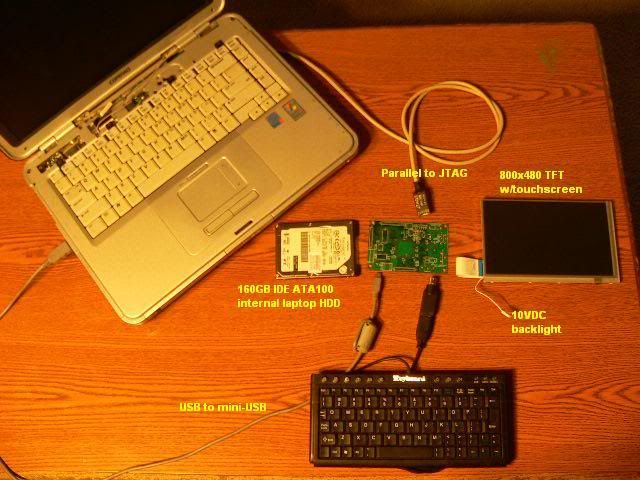
A size comparison:
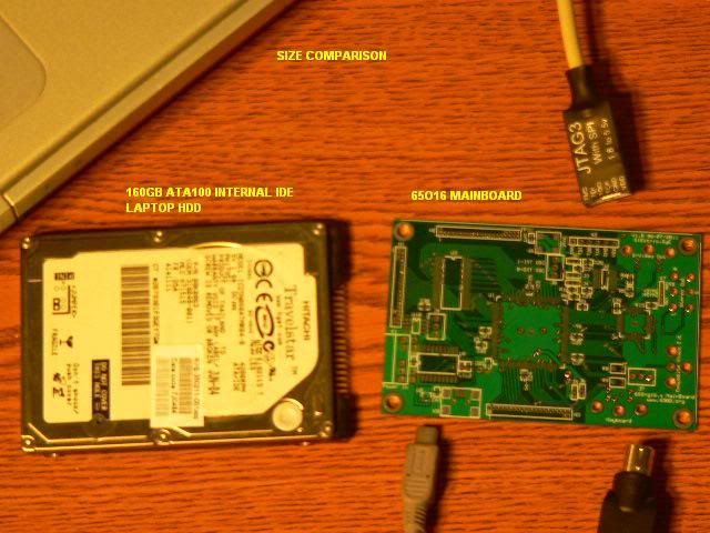
I like pics, but the concept stays true to my 6502SoC
here.
Posted: Sat Aug 06, 2011 12:30 am
by ElEctric_EyE
Now I can stop playing and start working...
Got all of the stuff from Digi-Key on the parts list today and all the connectors fit! Now I await my SMD tweezers, next tuesday, for soldering the 0603 parts. The 0603 parts are abit smaller than I would have preferred. These are the parts I mean to solder first as they are closest to the board and with the board clear I will have the best angles to get at them.
But I must start soldering something! Also I realized I must write down an assembly list... Also, time to step up the soldering station...
Posted: Sat Aug 06, 2011 6:16 am
by Arlet
The 0603 parts are abit smaller than I would have preferred. These are the parts I mean to solder first as they are closest to the board and with the board clear I will have the best angles to get at them.
I always do the TQFPs first, and then the 0603. I don't know what method you use for the TQFPs, but I always need room for the solder braid to fix the bridged pins. The 0603s can be in the way then.
Posted: Sat Aug 06, 2011 2:25 pm
by ElEctric_EyE
Well, I have used braid and it works well. I've also used a solder sucker in some spots. When I was attaching a 208-pin QFP to an adapter socket, braid seemed to do a good job.
I'm running into a problem now where my micro tipped butane soldering iron is totally lacking heating power for the larger connector mounting via's. And my larger radio shack soldering iron is junk. So, I've decided to make another investment in order to do this project and future projects right. It's only $100, seems like a great deal for it.
I found this while looking around. It's an
infra-red BGA reworking station.
Fine Pitch Slobbering
Posted: Sat Aug 06, 2011 6:01 pm
by BigDumbDinosaur
Well, I have used braid and it works well. I've also used a solder sucker in some spots. When I was attaching a 208-pin QFP to an adapter socket, braid seemed to do a good job.
I'm running into a problem now where my micro tipped butane soldering iron is totally lacking heating power for the larger connector mounting via's. And my larger radio shack soldering iron is junk. So, I've decided to make another investment in order to do this project and future projects right. It's only $100, seems like a great deal for
it.
I found this while looking around. It's an
infra-red BGA reworking station.
Sounds as though it's time to investigate making a reflow oven from a toaster-oven.

Re: Fine Pitch Slobbering
Posted: Sat Aug 06, 2011 11:52 pm
by ElEctric_EyE
BigDumbDinosaur wrote:
...Sounds as though it's time to investigate making a reflow oven from a toaster-oven.
Yeah, I remember us talking about soldering/unsoldering BGA style packages in another thread using a toaster oven, LOL. Such precise control over the heat there is... not!
This BGA style package I think requires many more layers than the 4 we're using now with EPCB. Mike J. over at FPGAARCADE has done it. Observing his log entries, it required many trips to China...
Nonetheless, he has board drawings on his site of his BGA based project.
As for me, everything is coming together for tue or wed of next week. Avnet parts will be here mon. Tweezers, and hopefully SMD desoldering station on tue, maybe wed, which are still my 2 days off at my new job... I negotiated . I need to correct some solder blobs, disgusting...
Another note: I am using 2 types of solder. 62/36/2 .015" silver bearing solder for SMD, and now standard .045 rosin core solder for the larger holes
Re: Fine Pitch Slobbering
Posted: Mon Aug 08, 2011 2:41 am
by BigDumbDinosaur
...Sounds as though it's time to investigate making a reflow oven from a toaster-oven.
Yeah, I remember us talking about soldering/unsoldering BGA style packages in another thread using a toaster oven, LOL. Such precise control over the heat there is... not!
This BGA style package I think requires many more layers than the 4 we're using now with EPCB. Mike J. over at FPGAARCADE has done it. Observing his log entries, it required many trips to China...
Nonetheless, he has board drawings on his site of his BGA based project.
He had to *go* to China, as in strap an airplane to his butt, just to get some PCBs made?
Another note: I am using 2 types of solder. 62/36/2 .015" silver bearing solder for SMD, and now standard .045 rosin core solder for the larger holes
Unless your PCB is RHOS, I'd skip the silver-bearing solder and stick with 63/37 rosin core for discrete parts. The silver-bearing stuff has no particular advantage, in my opinion, and merely increases how much heat you have to pour into the part to achieve a good joint.
Speaking of slobbering parts to PCBs, I got a burr under my saddle the other day about trying to figure a quick and dirty way to solder an SMT device to a PCB. So...using one of the spare POC V1 boards I have, I fooled around with using my small heat gun (has a vacuum cleaner style nozzle) to reflow a SOJ32 part. I applied plenty of liquid flux to the pads, a small dab to each pin on the part and placed it. I positioned the heat gun so it was as close as perpendicular to the PCB as possible and placed the nozzle very close to the part (about a half-inch away). Using the high heat setting, I gave the chip a blast of hot air until I saw the solder liquify and flow. I immediately cut off the heat, waited until it was clear the solder had solidified and felt the board in the vicinity of the part to see how hot it had gotten. It was quite warm but not enough to burn. Even the part wasn't all that hot. I let it cool for a few more minutes and then metered all 32 pins. All connections were good and there were no shorts between pins. At this point, I don't know if the part is actually functional but I'm going to slap some parts on the board when time permits and see if it'll run.
Now, I'm not saying that this is a suitable method for soldering up multiple SMT parts, but it could be okay as a rework procedure. The key to it, I think, is to use a smaller heat gun, not one of those kilowatt things that can strip the hide off a buffalo. Also, the metal pins and the pads absorb heat much faster than the PCB or the rest of the part, so it could be an acceptable process that won't trash parts. It certainly had no effect on the appearance of the PCB. The solder mask wasn't discolored on either side, no traces lifted, etc.
I'll report back when i have an opportunity to test.
MikeJ's FPGAArcade Replay Project Blog
Posted: Mon Aug 08, 2011 7:00 am
by BigEd
... Mike J. over at FPGAARCADE has done it. Observing his log entries, it required many trips to China...
Nonetheless, he has board drawings on his site of his BGA based project.
He had to *go* to China, as in strap an airplane to his butt, just to get some PCBs made?
Looks like he has taken several trips - and he's doing
prototype runs in quantities of some 10's of parts (ultimately to ship to developers), so these are indications of a serious project. Unfortunately the months go by, as they do for all of us.
Thanks EEye for the pointer to
MikeJ's blog - interesting read!
Cheers
Ed
Re: Fine Pitch Slobbering
Posted: Mon Aug 08, 2011 4:35 pm
by ElEctric_EyE
BigDumbDinosaur wrote:
...I fooled around with using my small heat gun (has a vacuum cleaner style nozzle) to reflow a SOJ32 part. I applied plenty of liquid flux to the pads, a small dab to each pin on the part and placed it. I positioned the heat gun so it was as close as perpendicular to the PCB as possible and placed the nozzle very close to the part (about a half-inch away). Using the high heat setting, I gave the chip a blast of hot air until I saw the solder liquify and flow...
So was this a new board you soldered the part to? and you didn't have to add any solder? I've used the .015" solder because it was so thin, not because it was silver bearing solder, and I could get such a small amount on the solder tip. It transferred solder to about 10 pins before I had to use more.
Posted: Mon Aug 08, 2011 4:56 pm
by Arlet
My standard solder is 0.7 mm (about 0.028"), Multicore 60/40 lead/tin alloy with mildly activated flux. My soldering iron is a Weller WS51, with ETH tip (0.031" screwdriver model).
For TQFPs I quickly solder all the pins, without worrying about bridges. Sometimes, I just make one giant bridge between all the pins. Then I use a piece of solder wick to clean everything up.
For fine pitch (0.5mm), I use clean pieces of wick, for bigger pitch (0.7mm), I use wick that's almost saturated with tin, so it leaves a nice residue. I usually don't use extra flux, but I try to work quickly, so the flux from the tin stays active during the entire process. Make sure everything is nice and hot, so you don't solder the wick to the pins, and move carefully.
For small components, like 0603, I put a tiny blob of tin on one pad, solder the part, and then do the other side.
Re: MikeJ's FPGAArcade Replay Project Blog
Posted: Tue Aug 09, 2011 12:36 am
by ElEctric_EyE
BigEd wrote:
...and he's doing prototype runs in quantities of some 10's of parts (ultimately to ship to developers), so these are indications of a serious project. Unfortunately the months go by, as they do for all of us...
Indeed, the months go by for us lone DIY'ers... It took 2 months alone for me to develop my relatively simple board.
On the same note though I would now like to make it known to all and send 2 of the 3 boards out to our "developers" here on 6502.org. The ones closest to this thread, IMO the ones who deserve it, and who are most likely to contribute to furthering the FPGA design, whether for profit or for sharing at least just a little. That would be Arlet and BigEd.
I am considering a 2nd run of a set of 3 more boards after I've made a few corrections others have pointed out. Flaws which should not hinder the operation of the board, but when fixed, should make it run better, namely the "pseudo analog ground plane" I tried to implement.
Anyway, the 2 beneficiaries are the 2 "teams" that put forth so much effort into their software for 65O16 development there in the Programming thread, namely Bitwise and teamtempest both...
Maybe I shouldn't have mentioned all this so soon, but we're approaching the crossroads... And so when this current board passes the test, the board should be quite capable, and not only according to me...