
Isn't the display only a small part of the project? Even if this display is obsolete, the advances you make might apply to other similar displays.
Not to mention, the project on the whole might be of interest to others, either now or in the future. Keep posting!
Daryl
Project: Digital Fuel Injector Pulse Width Analyzer
Last edited by 8BIT on Thu Nov 05, 2009 1:14 pm, edited 1 time in total.
-
BigDumbDinosaur

- Posts: 9428
- Joined: 28 May 2009
- Location: Midwestern USA (JB Pritzker’s dystopia)
- Contact:
Screw the Display—Keep Working
The display is a minor bump in the road. The meat and potatoes are in your circuit design and logic. You can always work out the interface to another display device once you're satisfied with how the core circuit is operating.
Incidentally, in your circuit you show an 'F138 decoder. The 'AC138 version has identical propagation times at 5 volts, but being CMOS, eats fewer electrons as it goes about its business. Unless you have logic that requires TTL voltage levels, you should abandon all 74LS' and 74F' logic where possible. In most cases, you can use 74ABT' or 74ACT' silicon to interface to TTL-level circuits and still achieve single digit nanosecond performance.
Incidentally, in your circuit you show an 'F138 decoder. The 'AC138 version has identical propagation times at 5 volts, but being CMOS, eats fewer electrons as it goes about its business. Unless you have logic that requires TTL voltage levels, you should abandon all 74LS' and 74F' logic where possible. In most cases, you can use 74ABT' or 74ACT' silicon to interface to TTL-level circuits and still achieve single digit nanosecond performance.
x86? We ain't got no x86. We don't NEED no stinking x86!
-
GARTHWILSON

- Forum Moderator
- Posts: 8775
- Joined: 30 Aug 2002
- Location: Southern California
- Contact:

-
ElEctric_EyE
- Posts: 3260
- Joined: 02 Mar 2009
- Location: OH, USA
I just wanted to see if anyone was interested. The only problem right now is that the display is discontinued, so now that I am making progress, I was asking myself what is the point of posting if noone could replicate what I am doing. But like 8bit said, the display is only part of the project. I was getting too wrapped up in the video part of it. But now I get to see all you lurkers anyway 
I'm going to make a video soon after I wire in an 8-bit ADC and finish the DRAWBOX routine. I'm done with the horizontal and vertical line routines, and should finish the DRAWBOX routine tonight. I'll save the diagonal line routine for later, that'll be a challenge. Without the delays, it clears the screen about 4 times faster than those 2 videos I have on youtube. Still this is not fast enough. I would like to copy the contents to RAM and run the "OS" from it. Right now I'm using an 8Kx8 EEPROM with access times of 70ns. The 32Kx8 SRAM has access times of 20ns. Right now with my present setup I can run at 7MHz max. How much faster could I run using the RAM? If I do opt to get the 640x480 display that's alot more display memory I will have to manipulate.
I'm going to make a video soon after I wire in an 8-bit ADC and finish the DRAWBOX routine. I'm done with the horizontal and vertical line routines, and should finish the DRAWBOX routine tonight. I'll save the diagonal line routine for later, that'll be a challenge. Without the delays, it clears the screen about 4 times faster than those 2 videos I have on youtube. Still this is not fast enough. I would like to copy the contents to RAM and run the "OS" from it. Right now I'm using an 8Kx8 EEPROM with access times of 70ns. The 32Kx8 SRAM has access times of 20ns. Right now with my present setup I can run at 7MHz max. How much faster could I run using the RAM? If I do opt to get the 640x480 display that's alot more display memory I will have to manipulate.
-
ElEctric_EyE
- Posts: 3260
- Joined: 02 Mar 2009
- Location: OH, USA
ElEctric_EyE wrote:
...I'll save the diagonal line routine for later, that'll be a challenge.
-
ElEctric_EyE
- Posts: 3260
- Joined: 02 Mar 2009
- Location: OH, USA
5x7 was still too large. Had to make a 3x5 character set. Also made the PLTCHAR subroutine recognize a charset variable that automatically does the vertical and horizontal spacing and character table offset. 2 Character sets so far. I would also like to do a 3rd character set, that's 16x16, for the startup screen.
It's been more than 20 years since I programmed 6502 assembly for graphic routines and I have been away from electronics for just about as long, but I really like the reward that comes from finishing a good subroutine. Even more than building a piece of hardware. Nice and compact, fast and clean. So anyway, so far I have written a little over 1K of code. These are the routines I've completed.
CLeaR SCReen.
XYCALCulate.
DRAW Vertical LiNe.
DRAW Horizontal LiNe.
DRAW BOX.
PLoT CHaR.
Now I am back to doing a subroutine I mentioned before but I never did get around to tackling it. I need to figure out how to display a 3 digit decimal number from an 8 bit hex value. Is there a better way than just doing a 256 value lookup table?
Things planned for tomorrow:
1) Wire up an ADC0820 and hook up a mic for simulating signals.
Things planned for the future:
1) Update videos on youtube.
2) Learning Macros for Michal Kowalski's Macroassembler.
3) Learning PICs and/or Atmel Atmega series.
I think the Atmel part is what I really need for frequency generation. I need to have a programmable 50/50 duty cycle frequency generator that can run sub 20MHz and have good divider resolution.
-
ElEctric_EyE
- Posts: 3260
- Joined: 02 Mar 2009
- Location: OH, USA
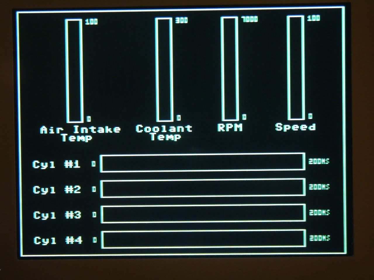
This will be the startup screen. All live data read from inputs will be put inside the boxes.
I am thinking about an alternate screen with large character's.. So you can switch between the fuel injector pulse widths (quick changing data), and the coolant temp, air temp, etc. (slow changing data). I will be looking at this datum while driving.
Notice as well, if I had a 640 H x 480 Vertical display, I could display another 4 cylinders, but all characters would be half sized...
EDIT:old image updated.
-
ElEctric_EyE
- Posts: 3260
- Joined: 02 Mar 2009
- Location: OH, USA
Re: Project: Automotive Fuel Injector Pulse Width Analyzer
ElEctric_EyE wrote:
...First and most importantly, the Throttle Position Sensor, along with the Coolant Temp Sensor, are expected to have the most effect on fuel injector pulse width. Other critical inputs which need consideration are: the Crankshaft Position Sensor, Camshaft Position Sensor, Mass Air Flow Sensor and/or Manifold Air Pressure sensors. Vehicle speed must be measured as well, along with Air Temp. Pre-Catalyst O2 sensor/s will be observed as well as post Catalyst. Post Catalyst sensor info will be observed only for simulation, for reasons to be explained later...
At this point, I realized there will be no need for the: Cam position sensor, MAF/MAP sensor or any of the oxygen sensors. Not at this point anyway. I need to observe fuel injector pulse widths to see where I can modify my driving skills to achieve max fuel economy within the restraints of EOM incar CPU programming. And then recompare after a supplemental fuel additive. And then take over control of the fuel injector PWM after that.
I expect all of the sensors I will be monitoring to be linear. The crankshaft position sensor will have to be referenced to 1 sec for a RPM display. This is an obvious linear sensor. The TPS, Coolant, Air Temp, and Speed hopefully will be linear . The plan is to manually measure each one of these sensors at 2 different lower speeds and then be able to interpolate all other readings, in between and above the initial measurements.
-
ElEctric_EyE
- Posts: 3260
- Joined: 02 Mar 2009
- Location: OH, USA
ElEctric_EyE wrote:
... These are the routines I've completed.
CLeaR SCReen.
XYCALCulate.
DRAW Vertical LiNe.
DRAW Horizontal LiNe.
DRAW BOX.
PLoT CHaR.
CLeaR SCReen.
XYCALCulate.
DRAW Vertical LiNe.
DRAW Horizontal LiNe.
DRAW BOX.
PLoT CHaR.
...I accidentally deleted all pics from Photobucket. I'll upload the originals soon...
I've not wired in the ADC yet, as I've mentioned I would ... Software is taking more time and my mind goes off in tangents. But I am looking at an 8 channel ADC, along with a multiplexed 8/16 bit counter to analyze the fuel injectors. Also I want to transmit the data wirelessly.
I am really interested in picture data next. Text is boring and now all the text routines have been completed. With a 65C02 at 6MHz, I want to make 65K color sprites/icons from, say a .JPG file. I'm in the process of doing research.
Next I'm going to try to take a pic from a cam, convert it to 16 bits, look at the datum in the hex editor, and then and see what it looks like on the display. I am thinking even if the colors aren't matched, there will be some kind of correlation.
If you can, 24bit BMP files are much easier, as there is typically no compression. Just a header and pixel data.
I read this link and was able to convert a 24bit bmp file to a compatible 8 bit image on my SBC-3 using a simple QBASIC program. Took 30 minutes from start to finish. Making sprites and background pictures should be simple. Conversion to other color depths is just a matter of using the most significant bits for each color from the 24 bit source.
http://local.wasp.uwa.edu.au/~pbourke/dataformats/bmp/
Hope that speeds things along!
Daryl
-
ElEctric_EyE
- Posts: 3260
- Joined: 02 Mar 2009
- Location: OH, USA
-
GARTHWILSON
- Forum Moderator
- Posts: 8775
- Joined: 30 Aug 2002
- Location: Southern California
- Contact:
I don't know if this is what you're talking about, but the very feature-loaded programer's text editor I use, MultiEdit by American Cybernetics in Arizona, has a hex mode that lets you edit hex code. It's all in rows and columns of two hex digits for each byte, with ASCII interpretation on the right if it's displayable.
For Intel Hex which is plain text, any text editor will work. I don't think MultiEdit can re-calculate the checksum byte at the end of an Intel Hex line, but if you're making just a few changes to a file, you could calculate it by hand.
For Intel Hex which is plain text, any text editor will work. I don't think MultiEdit can re-calculate the checksum byte at the end of an Intel Hex line, but if you're making just a few changes to a file, you could calculate it by hand.