Page 8 of 10
Re: My project with a w65c265s MCU.
Posted: Sun Aug 02, 2020 12:00 am
by BitWise
The hunt algorithm is very simple. I doesn't detect a RAM chip that repeats multiple times within a chip select range.
Re: My project with a w65c265s MCU.
Posted: Sun Aug 02, 2020 4:41 am
by BigEd
Try writing different things to each bank. You will then be able to see the aliasing.
Re: My project with a w65c265s MCU.
Posted: Tue Aug 04, 2020 12:49 am
by tokafondo
Well... For some reason, the EEPROM chip got stuck in a sort of "read only" mode... I can't write to it at all. So I think it's time to start again with the mainboard, because the lastest wiring was a total mess. I've seen breadboards with a lot of wires from here to there, but at least there was some air there. Mine was overcrowed.
So instead of debugging the EEPROM thing, I took the other circuit board and started to put sockets and wires to transfer the chips from the older to the newer one.
It now resembles a serious project. I still have to put VCC/VDD there, and the clock and reset circuits. But it's now less a mess...
I also put a jumper there, inside the 40 DIP socked of the second SRAM chip, to be able to select CS5 or CS7 for the /CE line of that chip.
Re: My project with a w65c265s MCU.
Posted: Sun Aug 09, 2020 3:33 pm
by tokafondo
Well, I finished the board swap, and now I have everything working again. The
read only mode the EEPROM got stuck in was surely a broken wire or something. Redoing the entire circuit in another board fixed it.
I also included some extras:
On the right, there is a jumper to tell the second RAM chip which chip select line it should answer to: CS5 or CS7.
On the left, there are two jumpers that should be telling the board which one of the four 32K banks of EEPROM memory it should be booting from. I achieved this by making the jumpers decide if the A15 or A16 lines should be tied to the pin of the MCU that drives them, or VSS, that effectively brings that pin low.
I tested this and at least for selecting the bank, it's working.
Re: My project with a w65c265s MCU.
Posted: Sun Aug 09, 2020 6:45 pm
by tokafondo
Got the graphics chip soldered in the adapter. Much easier than I thought. I just saw some youtube videos and I got it placed at first try. Also checked for shorts and continuity, and everything is OK!!
I have to get a regulator to feed this chip with 1.5v.
I'm scavenging from old computer PCBs again, as I did to get the 3.3v one.
Once I get it fed, I have to place the same wires I did with the memory chips, but with this one.
And then, start reverse engineering with a logic probe, the still-not-callibrated oscilloscope and the multimeter, the LCD from an old Nintendo DS I have here, because that would be the LCD I would be using.
Re: My project with a w65c265s MCU.
Posted: Sun Aug 09, 2020 6:55 pm
by BigEd
Well done! Surface mount soldering is increasingly part of our retro project world.
Re: My project with a w65c265s MCU.
Posted: Sun Aug 09, 2020 7:13 pm
by tokafondo
Thanks! In this case, this was required, as this chip does not have trough the hole packages, and I had to adapt it my self to the board.
After getting it connected, I will have a much more difficult challenge... Coding for all of this to work!!!
Re: My project with a w65c265s MCU.
Posted: Sat Aug 22, 2020 7:43 pm
by tokafondo
I just built a socket for the graphic chip from strips of 50 x 1 sockets.
I still have to wire the system bus (data, address, CS, OE and WE) lines, to have access to the internal 384K of RAM. I will link it to the CS6 pin of the '265s chip.
The chip works at 1.5v internally, but the I/O lines are 3.3v tolerant. So I need two VDD lines, marked COREVDD and IOVDD. It needs 11 (eleven!!) bypass capacitors and I ran out of them... I think I'll skip the capacitors by now and wire what I told earlier, plus the CLKI line, and also the pins that configure the chip to be 65xx compatible (8 bit direct addressing mode).
I don't think
not putting the capacitors would do anything bad, or will it?
Re: My project with a w65c265s MCU.
Posted: Sat Aug 22, 2020 7:45 pm
by BigEd
Missing out bypass caps is likely to result in unreliable operation, which makes debugging a case of chasing ghosts - not a good place to be!
Re: My project with a w65c265s MCU.
Posted: Wed Aug 26, 2020 11:04 pm
by tokafondo
Well... I placed all the 100nf capacitors and started to put inside the square two lines of VDD: one for 1.5v and another one for 3.3v.
But once I put the voltage regulator, It had a drop of voltage to 1.2v. I already had it working in another place of the board giving 1.5v but now it dropped to 1.2v.
So I got all the low value 1W resistors I had at hand and started combinations until I had a voltage divider that gives me 1.45v. It's right for me because the chip works from about 1.36v.
So I converted 3.3v to 1.45v using a lot of 1W resistors, but... Is that the right way to do it? They say it
can be done, but I don't know if it
should be done this way. Will it make the chip work worse?
I burnt several capacitor plastic
cases because the angle I put the solder iron tip. Inside the socket, the inner square carries 1.5v. The outer, 3.3v. And GND, outside the socket.
Should I go and buy a proper voltage regulator IC instead of this?
Re: My project with a w65c265s MCU.
Posted: Wed Aug 26, 2020 11:18 pm
by GARTHWILSON
I burnt several capacitor plastic cases because [...]
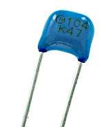
- monolithicCeramicCap.jpg (11.22 KiB) Viewed 1831 times
This shows up about five times actual size on my monitor.
Should I go and buy a proper voltage regulator IC instead of this?
Yes. A resistive voltage divider's output will depend on the load. A regulator's output will be quite firm across its load range.
Re: My project with a w65c265s MCU.
Posted: Wed Aug 26, 2020 11:48 pm
by tokafondo
I burnt several capacitor plastic cases because [...]
monolithicCeramicCap.jpg
This shows up about five times actual size on my monitor.
Thanks. I actually got some of these from an audio amplifier!! I'll have to ask the electronics store for ceramic ones, then.
Should I go and buy a proper voltage regulator IC instead of this?
Yes. A resistive voltage divider's output will depend on the load. A regulator's output will be quite firm across its load range.
Is there any chip that directly gives 1.5v output, with no need of regulator, like the 7805 does with 5v? I'll have to search...
Re: My project with a w65c265s MCU.
Posted: Thu Aug 27, 2020 7:01 am
by GARTHWILSON
Is there any chip that directly gives 1.5v output, with no need of [a] regulator, like the 7805 does with 5v? I'll have to search...
The 7805 is a regulator, a linear one. Commercial designs using 1.5V would usually use a switching regulator (or "switch-mode power supply," or "SMPS" for short) to improve efficiency. If you're not needing to run it off a small battery and make the battery (or a charge) last a long time, a linear regulator should be fine for hobby use. It's possible there are integrated switching regulators available for 1.5V, perhaps from Pololu, but even proper board layout to get good behavior from a switching regulator is beyond the capability of most hobbyists. I would recommend an LM317T which is a linear regulator in a TO-220 package and you set its output voltage with a pair of resistors. For 1.5V, do it like this:
- 1V5LM317T.gif (11.32 KiB) Viewed 1813 times
Again, make the capacitors monolithic ceramics.
Re: My project with a w65c265s MCU.
Posted: Fri Aug 28, 2020 3:35 pm
by ttlworks
ADP3338 is a 1.5V linear regulator, input voltage 2.7V..8V, 2.56€ at Mouser.
But it's SMD, it's pretty exotic, and LM317 can take more damage.
STS1005S1V5 is a 1.5V switch mode regulator, input voltage 3V..5.5V, 7.74€ at Mouser.
But to me it looks pretty exotic, too.
TR2005S1V5 is a 1.5V switch mode regulator with 3 pins, input voltage 3V..5.5V, 7.20€ at Mouser.
Neat thing.
;---
I second Garth:
If you want to do some hobby tinkering with what's available at the electronics shop "at the next corner", go for LM317:
it's cheap, it's supposed to be available everywhere, and it's not easy to destroy that chip (when not reversing the power supply by accident).
And by all means: use ceramic capacitors (low
ESR) in the power supply of your chips,
plastic film capacitors usually won't do for filtering voltage spikes out.
Re: My project with a w65c265s MCU.
Posted: Fri Aug 28, 2020 5:12 pm
by tokafondo
Thanks for suggestions, guys. I finally got back my APL1117 ripped off a gigabyte motherboard (which incidentally has a multiregulator chip that gives out several voltages) and got it regulated to 1.5v again.
And I finally got all the host cpu pins wired, so in theory I can access the internal memory and registers of the graphic chip.
I now have to socket it in and test it. Is should be able to initialize it so I can access the RAM, because on reset the registers are accessible but not the RAM itself.
Once I get the RAM accessible, I should be able to write to it, and read from it. It seems that even being able to do it, I should not use it to run code but just to store data. Here is the internal memory mapping of this chip.
EPSON do provide some tools to generate the right values to write to the registers and the order to be written, to initilize the chip. I'm waiting now for an adaptor for the LCD module and some step-up voltage regulators to be able to starting to test the Nintendo DS Lite LCD screen.