The ISE 9.2 software isn't perfect, but I've found as long as you have a schematic to work from, you can start a new project and enter the schematic fresh, and there won't be any problems. I've run into issues where I'll start modifying a schematic, and when I try to implement it, it gives netlist errors. Probably my fault but still, I have no complaints, I can get it to go through error checking and create the .jed file successfully...
Just to update, I'll post the final schematics with: discrete logic, the CPLD version that replaces the discrete logic, and the one with the SRAM window. None of it has been wired and tested, except for the discrete logic. I have some parts on order to implement the CPLD, so it'll be a couple weeks before I wire the last schematic up.
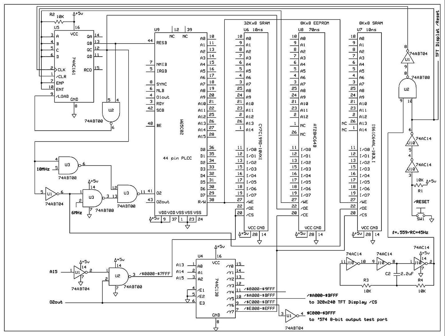
Discrete logic (old design):
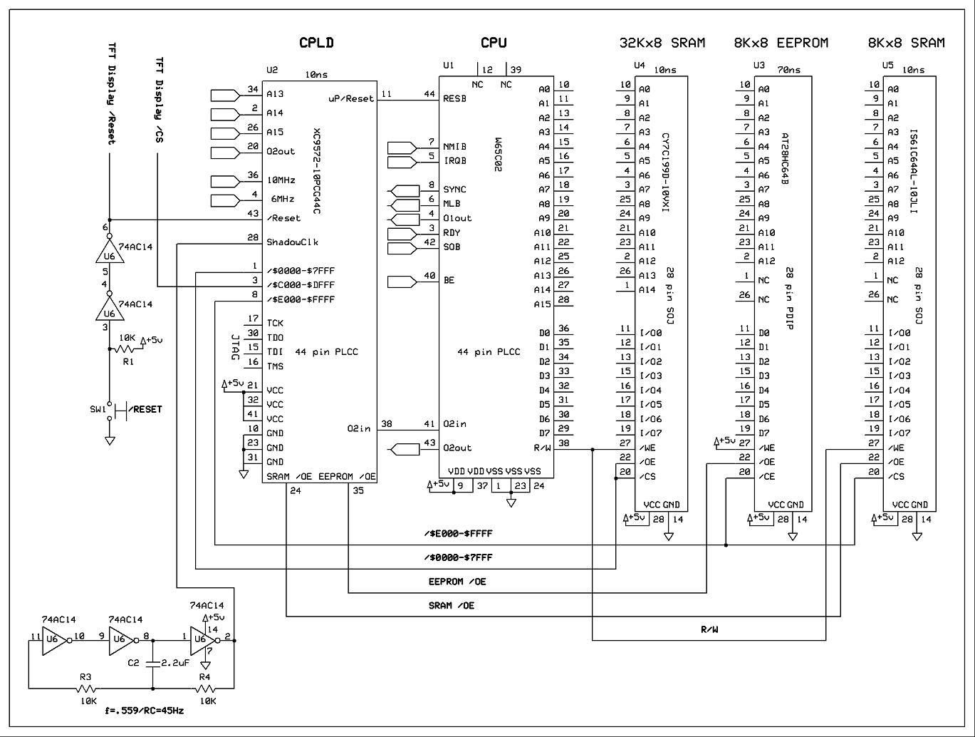
Using XC9572 CPLD to replace the discrete logic (old design):
Inside the XC9572 CPLD utilizing all but 2 pins (new design,compare to original): This new one utilizes 21% of macrocells, 13% of registers, & 92% of pins... At this point, I would like to maximize pin usage.
EDIT: Added a divide by 2 and 4 from the FastClk input so user can hardwire a select from onboard divider to SlowClk. Fixed _DE00DEFF latch signal from address decoding to 5 bit flip flop from active low to active high (DE00DEFF). (Utilizing 23% of macrocells, 16% of registers, & 98% of pins)
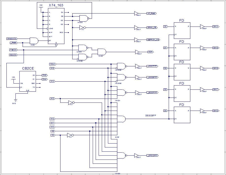
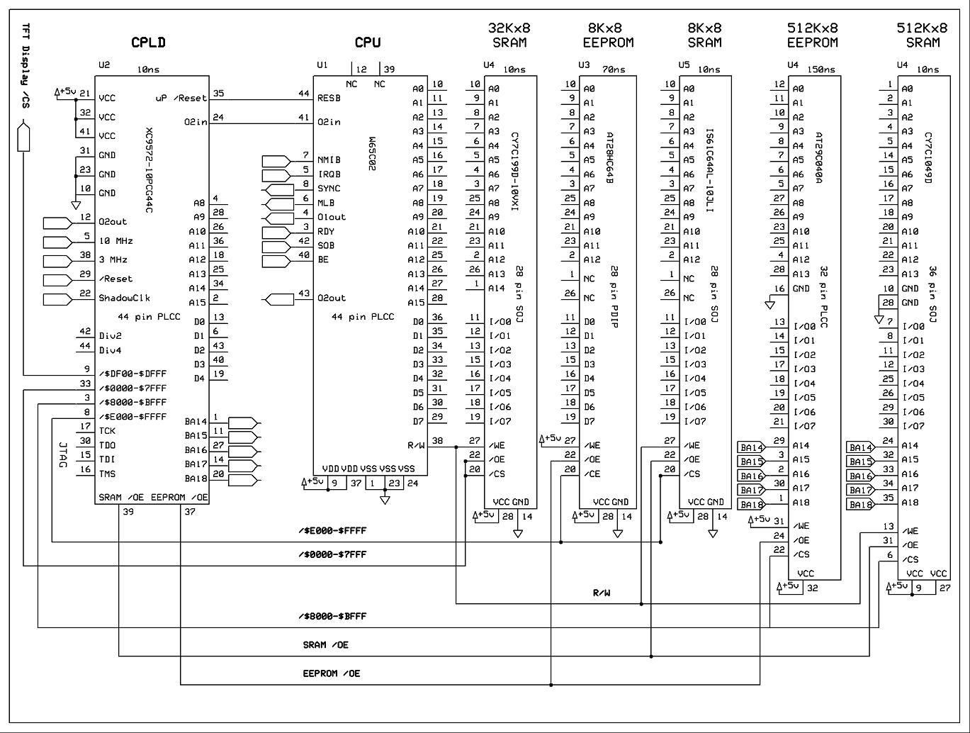
Updated schematic to control a 16K memory window into 512K, using the CPLD logic from the last pic. Different Icons/Pictures, and Fonts will go into this space (right now my character fonts are occupying 4K out of the 8K EEPROM, and I am quickly running out of programming space)... It will be copied into faster RAM just like the OS, so the whole system can run @10MHz. I had to slow down the clock speed from 6MHz to 3MHz, to do the EEPROM to SRAM copy, due to the slow (150ns) 512Kx8 EEPROM. I'll be wiring it up in a week or two... (I ordered 2 oscillators 10MHz and 14.31818MHz, so the 10MHz and 3MHz speeds are not exact speeds on the schematic)