6502 as a VGA controller

For discussing the 65xx hardware itself or electronics projects.
plasmo
Posts: 1273
Joined: 21 Dec 2018
Location: Albuquerque NM USA

6502 as a VGA controller

Post by plasmo »

Since it is possible to run W65C02 at 25.175MHz, I wonder how it can serve as a VGA controller with a little bit of glue logic.

VGA needs 3 signals, vertical sync, horizontal sync, and video out. Video out is fastest at 25.175MHz pixel rate; horizontal sync is derived from modulo-800 of the 25.175MHz; and vertical sync is modulo-525 of horizontal sync. Video out is too fast for 6502 to bit bang but can be supported with a 8-bit shift register that 6502 writes to every 8 clocks; horizontal & vertical sync can be software generated.

What can 6502 do in 8 clocks? It needs to fetch graphic data from memory, one fetch every 8 clocks. I'm thinking something like:

Code: Select all

LDA (zp),y
INY
LDA (zp),y
INY
...
repeated 80 times to generate one line of 640 pixel.

Instruction memory is 0x0-0x3FFF and graphic memory is 0x4000 and above. Hardware needs to load data fetched by the LDA instruction into a 8-bit shift register. Any access with addresses A14 or A15 high is to be loaded into the shift register. Horizontal sync and vertical sync are outputs of flip flops written by 6502.

This scheme is for monochrome VGA. Color needs multiple plane of memory and shift registers for R/G/B video which can become complicated rapidly.

Thoughts?

PS, it just occurs to me that this may already has been done. Apology if so and I'd appreciate a link.
User avatar
BigEd
Posts: 11463
Joined: 11 Dec 2008
Location: England
Contact:

Re: 6502 as a VGA controller

Post by BigEd »

I like the idea of a peripheral which snoops on read accesses!
User avatar
Dr Jefyll
Posts: 3525
Joined: 11 Dec 2009
Location: Ontario, Canada
Contact:

Re: 6502 as a VGA controller

Post by Dr Jefyll »

You may find an Ultra-fast output port using 65C02 illegal instructions helpful.

For starters, it'd be an extremely fast way to output horizontal and vertical sync pulses -- and, in regard to the horizontal sync pulse, you may welcome that extra speed. The horizontal retrace period is fairly brief, and during that time you'll also have other housekeeping to manage (such as updating the value in your zero-pg pointer).

More intriguingly, you could tap into the same "illegal instruction" circuit in order to derive a the cue for the shift register to load. Possibly there'd be an advantage to getting the cue that way, instead of generating it based on access to a certain portion of the address space.

One disadvantage of getting the cue that way is, the illegal instruction consumes a cycle... and you may or may not be able to afford that, depending on whether the LDA (z-pg),Y is expected to generate a page crossing.

-- Jeff
In 1988 my 65C02 got six new registers and 44 new full-speed instructions!
https://laughtonelectronics.com/Arcana/ ... mmary.html
plasmo
Posts: 1273
Joined: 21 Dec 2018
Location: Albuquerque NM USA

Re: 6502 as a VGA controller

Post by plasmo »

The illegal instruction is very cool! It maybe a good way to assign color attributes of a 8-pixel block. That is 5-bits of color. Thanks!
Bill
User avatar
Dr Jefyll
Posts: 3525
Joined: 11 Dec 2009
Location: Ontario, Canada
Contact:

Re: 6502 as a VGA controller

Post by Dr Jefyll »

Quote:
That is 5-bits of color. Thanks!
You're welcome. Just remember, on a WDC processer you'll need to avoid the STP and WAI instructions, which means you don't have unrestricted access to all 5-bit combinations -- only 30 of the 32 combinations are allowed.

I'm also thinking about your LDA (zpg),Y / INY ditty. Getting it to repeat exactly once every 8 cycles means you'll need to somehow account for the fact that LDA (zpg),Y may be either 5 or 6 cycles, depending whether there's a page crossing.

If you're interested I'll draw up a scheme that guarantees 8 cycles despite the presence or absence of page crossings, gives you unrestricted access to 5 or more color bits (albeit consuming 5 or more cycles), and lets you output video data from virtually anywhere in the memory map (not just from $4000 and up).
In 1988 my 65C02 got six new registers and 44 new full-speed instructions!
https://laughtonelectronics.com/Arcana/ ... mmary.html
plasmo
Posts: 1273
Joined: 21 Dec 2018
Location: Albuquerque NM USA

Re: 6502 as a VGA controller

Post by plasmo »

Yes, I love to hear your scheme. Thank you.

I'm thinking of fitting three 80 bytes (640 pixels per line) in a page, so I don't need to worry about crossing a page. Alternatively it can be 64 bytes per line (512 pixels per line) which packed into a page nicely and give me more time with horizontal retrace to do housekeeping.

My plan is to rework CRC65's CPLD code to add the 8-bit shift register and latches associated with Vsync and Hsync. The board has been proven to run to 29.5mhz and I can change CPLD design easily.
Bill
User avatar
drogon
Posts: 1671
Joined: 14 Feb 2018
Location: Scotland
Contact:

Re: 6502 as a VGA controller

Post by drogon »

plasmo wrote:
Thoughts?
The thing that always goes through my mind with stuff like this is the sheer quantity of RAM needed...

So 640x480 at 1bpp needs 37.5KB of RAM.

And then the CPU cycles left over during H/V sync to do actual "work" like drawing lines, etc., ...

Bit it is do-able - e.g. the highest resolution mode on the BBC Micro was 640x256x1 and needed 20KB but it was very usable and fast enough - 2Mhz 6502.

If you did the odd/even clock thing with 2 x 65C02's ... One to handle the display, the other to draw the lines and so on then it might be much more usable. More-so if you arranged the 'drawing' 65C02 to have a sort of 'shadow' memory system, so toggle a bit and the graphics RAM is mapped in so it can modify it, then toggle another bit for program data RAM or something. (BBC Masters did this to give 32KB usable RAM, 20KB video RAM and 32KB ROM+IO)

Racing the beam is well known of-course (e.g. Atari 2600) so the 6502 doing the display function is essentially one big loop of memory accesses with strict VGA timings.

An interesting thing to see might be the BBC Micro "mode 0" version of the Bad Apple video. It runs the TV output in 640x512 mode interlaced (so beam races the 2 interlaced fields in 20KB of RAM) - the way i works is interesting, but imagine you have a 280MB program in ASM that's doing nothing more than LDA... STA, STA, STA, STA, etc. synchronised with the TV refresh to play with video and throw samples at the sound system... https://www.youtube.com/watch?v=D_ta5QxBSMk

-Gordon
--
Gordon Henderson.
See my Ruby 6502 and 65816 SBC projects here: https://projects.drogon.net/ruby/
User avatar
Dr Jefyll
Posts: 3525
Joined: 11 Dec 2009
Location: Ontario, Canada
Contact:

Re: 6502 as a VGA controller

Post by Dr Jefyll »

drogon wrote:
And then the CPU cycles left over during H/V sync to do actual "work" like drawing lines, etc., ...
Yes, video schemes that directly involve the CPU can be appealingly simple but they hog a lot of cycles, leaving fewer for Real Work. It's a tradeoff.
drogon wrote:
imagine you have a 280MB program in ASM that's doing nothing more than LDA... STA, STA, STA, STA, etc. synchronised with the TV refresh
This sounds a bit similar to the "Cheap Video" approach made popular by Don Lancaster. In his case the "ASM" simply came from a tiny (typically 32-byte) ROM. A large chunk of the 65xx memory map would activate the same tiny ROM, so of course there were numerous aliased images of the same 32-byte device.

But nowadays RAM is so cheap that the aliasing trick has less appeal. You can just squander a large amount of real memory instead. I wrote about Cheap Video here.
In 1988 my 65C02 got six new registers and 44 new full-speed instructions!
https://laughtonelectronics.com/Arcana/ ... mmary.html
User avatar
Dr Jefyll
Posts: 3525
Joined: 11 Dec 2009
Location: Ontario, Canada
Contact:

Re: 6502 as a VGA controller

Post by Dr Jefyll »

Alright, here's my followup to the "illegal instruction" VGA plan. But firstly some background... Earlier I mentioned the Ultra-fast output port using 65C02 illegal instructions, and I have edited that post to include a new option, one which also plays a role in the VGA idea. As shown below, the new arrangement provides 8 one-bit ports, each of which can be individually written using a 1-byte, 1-cycle NOP from Column 3.
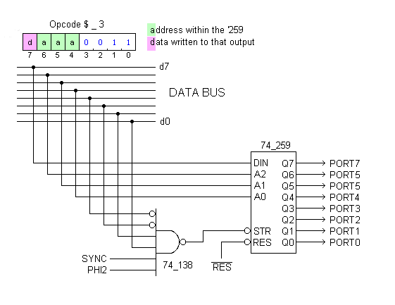
74_259 approach allows 8 individually writable bits
Ultra-fast_65c02_output_port using a '259 .png (5.9 KiB) Viewed 82839 times
Adding to that, the circuit below also responds to opcodes in Column 1. (These are not illegal.)
VGA controller.png
The opcodes in Column 1 are all either (z-pg,X) mode or (z-pg),Y mode, and it's the latter that appear in Bill's little ditty:

Code: Select all

LDA (z-pg),y
INY         ;the 2-inst'n sequence repeats 80 times to generate one line of 640 pixels
The LDA (zp),y opcode -- or any other (zp),y or (zp,X) opcode -- will cause the /COL_1 signal to go low at the end of the cycle during which the opcode is fetched. This gets inverted, and a one-cycle high subsequently makes its way through a delay line that's formed by 5 sections of a 74_174 hex D flipflop.

Referring to the cycle description included at the bottom of the diagram, we see that only cycles 5 and 6 will vary according to presence of a page crossing.
  • With a page crossing, cycle 5 is a CPU "internal operation." Cycle 6 is when the data access occurs and cycle 6 is when the Video Shift Register loads.
  • Without a page crossing, cycle 5 is when the data access occurs. Bus capacitance preserves this data for an extra cycle because on cycle 6 the data bus floats. Cycle 6 is when the Video Shift Register loads. The CPU is trying to fetch the next opcode during cycle 6, and that's why SYNC goes high... floating the bus and pulling RDY low for a single cycle.
There are some incidental details to attend to. The altered behavior of (z-pg),Y instructions exactly suits our needs for video, but we need a way to turn off the new behavior when not dealing with video. I've connected Q0 of the '259 so that a 1-byte, 1-cycle NOP can enable or inhibit the special response to Column_1 opcodes.

Q1 and Q2 of the '259 are shown as VSYNC and HSYNC outputs, and all the other bits remain available for whatever. They could be used to select colors, for example. Or... by adding another gate or two they could cause various other entire 64K regions to be activated during cycles 5 and 6!


Because it decodes instructions, this "video" scheme provides a potential means to let you read and write data of any kind from several, perhaps dozens, of other 64K banks at will.

I'll develop this idea further in a separate post, perhaps. But for now let me point out a highly pertinent point, and it is this: instruction decoding lets us know when the special memory access will occur. That's a crucial contrast with ordinary banking schemes, which rely on address decoding to tell us "when." :!:

If the "when" question ceases to rely on address decoding then you eliminate the regrettable need for the "window" -- a peephole within the 64K space -- that'd be necessary to trigger the address decoder. Instead of accessing the beyond-64K region as a series of peephole-sized chunks, you can access it in units which are each a full 64K. Peepholes suffice for some applications, but if you care at all about treating the new memory as a linear space (containing very large arrays, for example) then 64K units (similar to what the the 65816 uses, BTW) will perform a lot faster and give you fewer gray hairs than working through a peephole, IMO.

-- Jeff
Last edited by Dr Jefyll on Sun Mar 07, 2021 3:25 pm, edited 2 times in total.
In 1988 my 65C02 got six new registers and 44 new full-speed instructions!
https://laughtonelectronics.com/Arcana/ ... mmary.html
plasmo
Posts: 1273
Joined: 21 Dec 2018
Location: Albuquerque NM USA

Re: 6502 as a VGA controller

Post by plasmo »

It is really good to see how in-depth understanding of a processor can bring different solution to a problem. Once we do our own instruction decode, customization of instructions become possible. The way 65C02 executes column 3 illegal instruction in one cycle is really useful knowledge. For me, the col3 illegal instructions are too valuable for HSync and VSync. Combinatorial logic in CPLD is essentially free so I can provide address decode for HSync and VSync at the cost of 2 macrocells. I want to save the Col3 illegal instructions (ILLx) for color like this:

Code: Select all

 ILLx		;set color attribute of next 8 pixels
 LDA (zp),y	;fetch 8 pixel, repeat 80 times to form one 640-pixel line
 INY
...repeat 80 times...
It takes 8 clock cycles to execute the above 3 instruction. I can avoid page boundary by packing three 80-byte rows in a page. The 5-bit data can be latched to drive color lookup table. I can dance around the STP and WAI instructions.

For the near term path-finding with CRC65, I stripped out the CF interface logic; simplify the bootstrap ROM so it will always boot from serial port; added the 8-pixel shift register and address decode associated with horizontal and vertical sync. It is still a monochrome design and fit within the existing 64-macrocell CPLD (ATF1504 or equivalent). I'll do a quick prototype and see how well this concept works.
Bill
plasmo
Posts: 1273
Joined: 21 Dec 2018
Location: Albuquerque NM USA

Re: 6502 as a VGA controller

Post by plasmo »

I modified a CRC65 SBC:
* 25.175MHz CPU clock
* Replace CF interface signals with VGA's Hsync, Vsync, Video out
* Replace CF adapter with a 15-pin VGA connector
* CPLD changes:
- Smaller, 32-byte CPLD ROM that can only bootstrap serially
- 8-bit pixel shift register capture and shift data bus in address range 0x4000-0xEFFF
- 2 latches for VSync and HSync

Program is located in 0x0-0x3FFF. It basically toggle horizontal sync on and off followed by 80 set of

Code: Select all

.byte 3		;col-3 illegal instruction
LDA ($b0),y
INY
After 480 lines, it continue to generate HSync, but blank out the video output for 45 lines. It also generates vertical sync during the 45-line video blanking period. After every power cycle, program is loaded serially with the help of TeraTerm macro.

After much fiddling around, I'm able to generate stable video output suitable for display on a small 9" LCD VGA monitor. The problem is the software-generated HSync and VSync MUST be exactly the same or the display will flicker or even not lock in. That restriction is not too difficult to meet during the 480 lines of active video, but during vertical retrace where real work is being done, the requirement of generating precise horizontal sync is difficult to do, at least for newbie programmer like myself.

Two approaches:
1. A software framework and cycle accurate simulator to help me writing program for video data manipulation and still generating precise horizontal sync pulses
2. 10-bit counter in hardware that generates horizontal sync and interrupt.

#2 approach is obviously the better approach, but I may not have the spare resource in CPLD for hardware-assisted HSync generation.

I will trudge along...
Bill
Attachments
DSC_65020311.jpg
DSC_65030311.jpg
User avatar
Dr Jefyll
Posts: 3525
Joined: 11 Dec 2009
Location: Ontario, Canada
Contact:

Re: 6502 as a VGA controller

Post by Dr Jefyll »

plasmo wrote:
2. 10-bit counter in hardware that generates horizontal sync and interrupt.
We recently had a thread on generating Video Sync. This circuit is probably the smallest, physically.

Code: Select all

.byte 3		;col-3 illegal instruction
LDA ($b0),y
INY
Congratulations on creating your own custom instruction!

And you could easily take the idea further. Besides loading the shift register on cycle 5 of the LDA (zpg),Y you could also activate an alternative 64K (or larger) space on that cycle. The alternative 64K would be great for pixel data, of course, but you could stash other stuff in there, too.

On a related note, I hope you're following this. Cheap Video is a little gnarlier than what you're doing, but it fetches data at a rate that's 8 times as fast. And that opens the door for higher resolution and/or color.

-- Jeff
In 1988 my 65C02 got six new registers and 44 new full-speed instructions!
https://laughtonelectronics.com/Arcana/ ... mmary.html
plasmo
Posts: 1273
Joined: 21 Dec 2018
Location: Albuquerque NM USA

Re: 6502 as a VGA controller

Post by plasmo »

I didn't think there are room in the 64-macrocell CPLD for a 10-bit counter, but after several tries, I did managed to squeeze in a 10-bit modulo-800 counter to generate horizontal sync in hardware. I do need to make a few cuts and jumpers on the existing board to make it work, but if it really works as I've hoped, it can greatly simplify the video generation process. The existing board can handle monochrome 640x480 graphic, to go to color I'll need more memory and bigger CPLD.

I still have Don Lancaster's TTL Cookbook and CMOS Cookbook. He is a pioneer and prolific writer.
Bill
plasmo
Posts: 1273
Joined: 21 Dec 2018
Location: Albuquerque NM USA

Re: 6502 as a VGA controller

Post by plasmo »

This picture can be displayed with software generated Horizontal Sync and Vertical Sync, but the program is tightly constrained because the HSync must be exactly the same, all the time, even during the vertical retrace interval. By using a 10-bit counter in CPLD to generate HSync as well as an interrupt to 6502, the 6502 software only need to provide 80 bytes of data per horizontal scan during the active video portion. During the vertical retrace period, 6502 is free to do other tasks, such as manipulation of graphic data, without having to deal with the tight timing constraints of generating horizontal sync. At 60Hz frame rate, the vertical retrace time is 1.4 millisecond per frame or 86mS of free time per second. That may seem very little time, but since 6502 is running 25.175MHz, it can perform the task of a 2MHz 6502 in 86 milliseconds.

Attached is the top level CPLD design in schematic. The CPLD contains a 115200 baud serial port, a small (32 bytes) bootstrap ROM, address decode for RAM, serial port, video register, modulo-800 horizontal sync generator, vertical sync register, and parallel-to-serial pixel shift register. This 64-macrocell CPLD is actually over 110% utilized; the initial macrocell utilization was 71, but reduced to 64 macrocells after optimization. It fits, barely.

The picture data file is generated with 'image2cpp' which can convert an image to black & white and generate the correct data format suitable for displaying.
Attachments
DSC_65040313.jpg
topCPLD_VGA65.pdf
(18.93 KiB) Downloaded 292 times
User avatar
floobydust
Posts: 1394
Joined: 05 Mar 2013

Re: 6502 as a VGA controller

Post by floobydust »

That's quite impressive! But like you said, running the CPU at 25MHz does yield some good performance. Based on the tight timing constraints to generate video signals, it reminded of the old Atari Tempest game. I have the schematics for this somewhere... but, the entire gameplay was managed by a one-shot timer triggering the NMI on the 6502. The IRQ line wasn't used. Tempest was one of my all time favorite games way back... and they did that with a 1.8MHz 6502. I guess my point is, if you were to have any issues with a missed IRQ, that would show up as a video sync issue, so perhaps an alternate approach would be to use the NMI line and have it's routine handle the video timing.
Post Reply